
This website uses cookies so that we can provide you with the best user experience possible. Cookie information is stored in your browser and performs functions such as recognising you when you return to our website and helping our team to understand which sections of the website you find most interesting and useful.


ITEMLIST
Products Infomation

- Products by Category
- Electronic Measuring Instruments
- Electrical Safety Testers / Measuing Instruments
- MICROTEST Impulse Winding Tester 7750
Using non-destructive high-speed pulse testing voltage technology to measure insulation defects in wound components, comparing the damping attenuation waveforms generated by inductance and capacitance resonance to identify defective products.
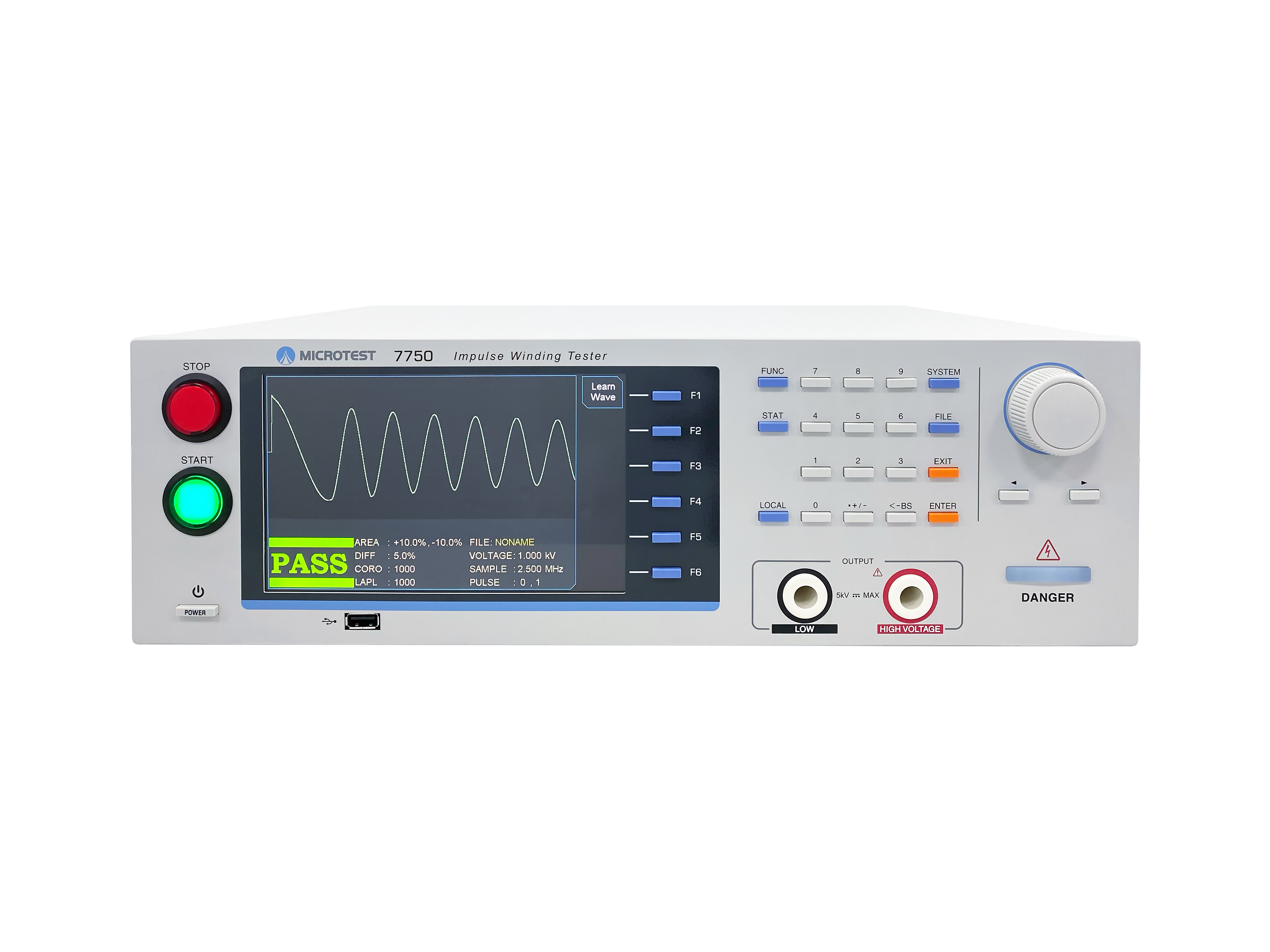
MICROTEST 7750 is an advanced Impulse Winding Tester with a faster color display screen. It provides pulse voltage outputs of 1200V/5200V/10000V and utilizes high-speed sampling technology at 200MHz/9 bits. It offers various comparison modes such as total area, area difference, corona count, jitter count, second-order differentiation, and waveform comparison. With a testing speed of up to 10 times per second, it is ideal for high-speed production lines.
For testing small components, the optional 7750-1 tester comes with the FX-IM0001 four-wire SMD component testing fixture. It features voltage compensation to minimize voltage errors caused by wiring and equivalent inductance, ensuring accurate quality control for products with small inductance.
Impulse Winding Tester
Model:
7750
Maker:
MICROTEST
The MICROTEST 7750 Interlayer Short Circuit Tester is designed for reliable insulation quality testing of high- and low-winding components. It utilizes non-destructive pulse voltage for waveform sampling and comparison, effectively detecting insulation issues in motors, transformers, BL inductors, and other components.
It supports pulse voltage outputs of 1200V, 5200V, and 10000V respectively, and employs 200MHz high-speed sampling technology to analyze subtle discharge faults. It offers six analysis and comparison modes, including total area comparison, area difference comparison, corona number comparison, jitter number comparison, second derivative comparison, and waveform comparison mode. With a testing speed of up to 10 times per second, it is the optimal choice for automatic production lines of winding components.
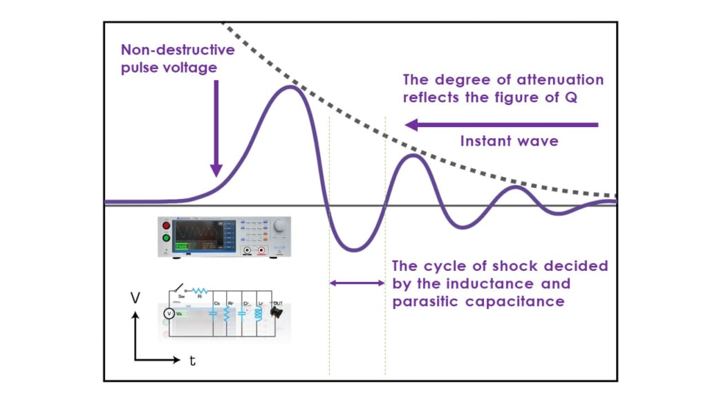
By applying a pulse voltage to the terminals of the winding coil, a damped oscillation waveform is generated through L/C resonance without damaging the test object. This allows for the comparison of instantaneous waveforms between a standard reference and the test object, enabling the early detection of faults such as interturn short circuits, internal coil defects, or insulation flaws in the magnetic core. This method ensures the quality and longevity of the product.
_The internal capacitor Cs of the instrument is connected in parallel with the external test object inductance Lr.
_The instrument outputs a set of high-speed pulse voltages to the parallel circuit.
_This generates a resonance between the inductance L and the capacitor C
The following electrical characteristics
have changed as a result of the defective product
_Inductance of the coil
_Quality factor (Q value)
_Difference in coil turns (voltage difference)
_Variations in magnetic core material
_Short-circuits between windings inside the coil
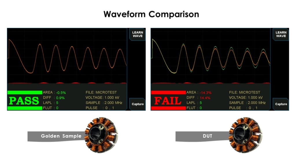
It supports six analysis and comparison modes, enabling the analysis and detection of insulation short-circuit issues in different winding components.
_Total area comparison
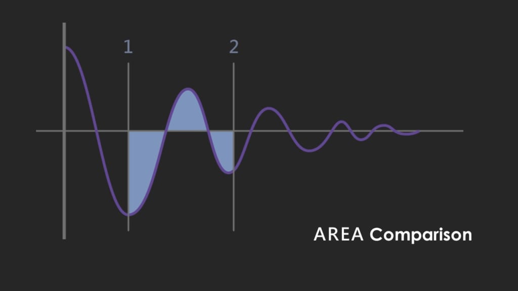
In the range from 1 to 2 as shown in the diagram, a comparison of the waveform area of the test coil is performed. When an interlayer short-circuit occurs in the test object, the energy loss of the coil increases, causing the damping coefficient of the resonance to increase. As a result, the resonance amplitude decreases, and the total area also decreases. This is the fundamental parameter for detecting interlayer short-circuits.
_Differential area comparison
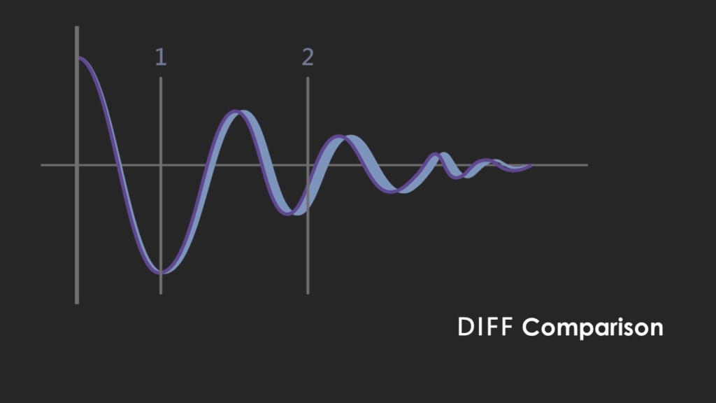
The difference between the point-to-point waveform areas of the standard sample and the test product is referred to as the “area difference.” When an inter-turn short-circuit occurs in the test object, the inductance decreases (similar to when the secondary winding of a transformer is short-circuited, the inductance of the primary winding decreases),resulting in a change in the oscillation frequency of the latter part of the waveform and a shift in the phase of the resonant waveform. Consequently, the area difference also changes.
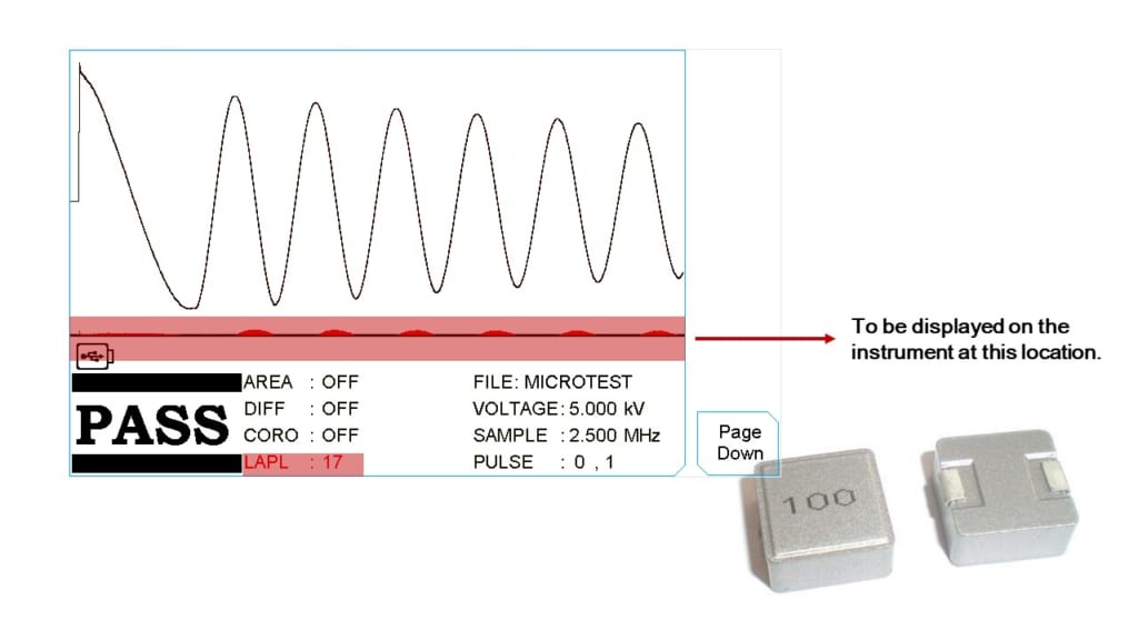
_LAPLACIAN Comparison
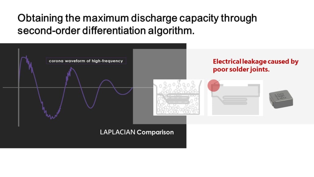
In the case of poor insulation quality of the coil, discharges occur under high-voltage impulses, causing rapid changes in the oscillation waveform. By utilizing the second-order differentiation algorithm of the MICROTEST 7750, the highest discharge level can be obtained.
This effectively detects quality issues such as leakage due to faulty solder joints in integrated molded inductors.
_COMP Comparison
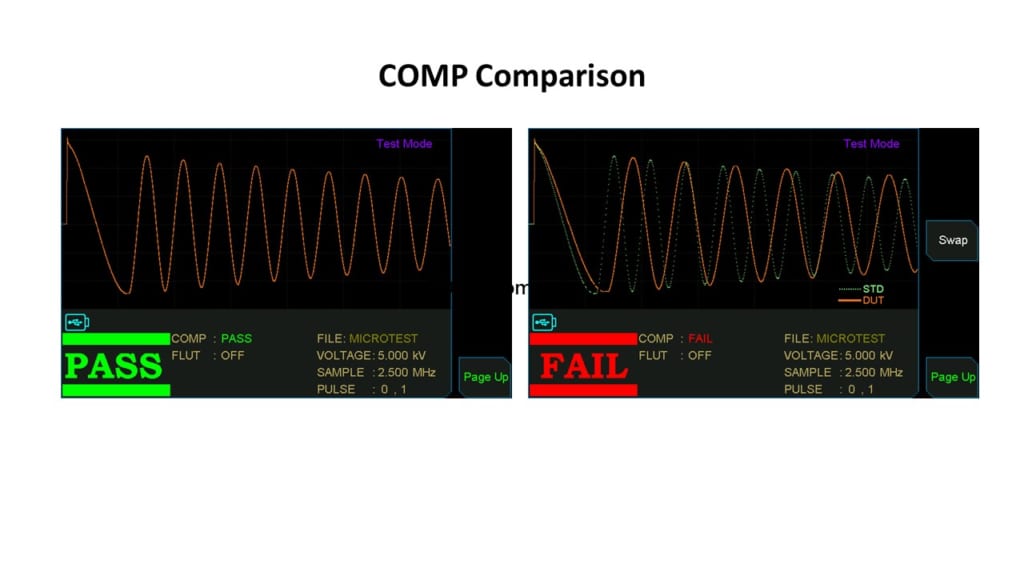 By setting an allowable waveform range for the standard wave, this feature can simultaneously determine the amplitude and phase of the resonant wave. It enhances the detection capability of inter-turn short circuits.
_FLUT Comparison
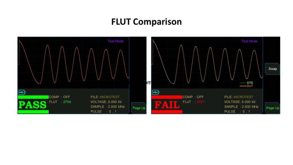
When there is inter-turn discharge in the winding coil, the waveform will exhibit tremors or fluctuations. Therefore, the instrument quantifies the degree of waveform tremors into numerical values for comparison.
Features
Lowest Inductance (≥0.1μH)
High voltage calibration
programmable impulse voltage
200MHz/9bit High Impulse Test Sampling Rate
Total Area Comparison
Differential Area Comparison
Corona Comparison
LAPLACIAN Comparison
Voltage Compensation Function
Application
Molding Power inductors (Molding Choke)
Molding Power inductors are commonly used in energy storage and filtering circuits of EV motor drive systems.
They provide stable power supply and suppress electromagnetic interference for high-frequency current pulses.
During the manufacturing process of integrated molded inductors, there can be issues such as conductor or magnetic powder material overflow into unintended structures, causing interlayer short circuits.
Uneven electroplating of the conductor material can also result in abnormal conducting paths and interlayer short circuits. By utilizing the second-order differentiation algorithm of the 7750, the highest discharge level can be obtained, effectively detecting quality issues
such as leakage caused by faulty solder joints in integrated molded inductors.
Winding components such as motors and transformers
With the increasing frequency of household electrical power sources, winding components in long-term operation may experience localized discharge due to poor internal insulation or incomplete short circuits within the coil. This can lead to a deterioration in the insulation performance of components such as motors and transformers.
Prolonged exposure to severe localized discharge can even result in breakdown risks. Therefore, relying solely on short-duration withstand voltage tests in the manufacturing process is insufficient to truly evaluate the reliability of winding components. It is necessary to conduct partial discharge testing using a nondestructive pulse voltage method. This involves generating a damped waveform through resonance between the inductance (L) and capacitance (C). By analyzing and comparing the waveforms, interlayer short circuit defects can be detected.
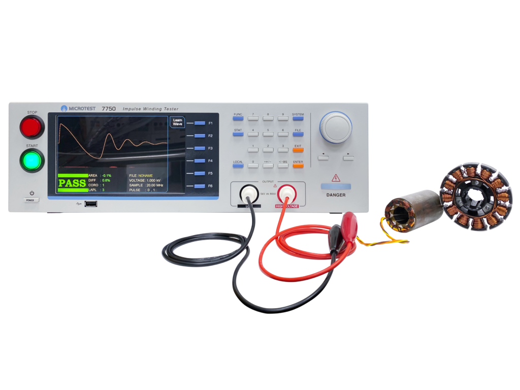
7750 Impulse Winding Tester
Specifications
Selection
| 7750-1 | |
| Impulse Voltage | 10V-1200V |
| Lowest Inductance | ≥0.1μH |
| Voltage Resolution | 0.1V |
| Voltage Accuracy | ±(1% of setting + 5V) |
| Pulse Energy | 0.028 joule |
| 7750-5 | |
| Impulse Voltage | 100V-5200V |
| Lowest Inductance | ≥10μH |
| Voltage Resolution | 1V |
| Voltage Accuracy | ±(1% of setting + 10V) |
| Pulse Energy | 0.5 joule |
| 7750-10 | |
| Impulse Voltage | 200V-10000V |
| Lowest Inductance | ≥20μH |
| Voltage Resolution | 5V |
| Voltage Accuracy | ±(1% of setting + 20V) |
| Pulse Energy | 2 joule |
SPEC
| Model | 7750-1 / 7750-5 / 7750-10 |
| Sampling Rate | 200MHz/9 bit |
| Pulse Number | Max. 32 |
| Input Impedance | 20MΩ |
| Measurement Statistics | ● |
| Breakdown Voltage | ● |
| Measurement Time | 10 times/second |
| Provides 6 waveform comparison |
| nTotal area comparison |
| nDifferential area comparison |
| nLAPLACIAN Comparison |
| nCorona comparison |
| nCOMP Comparison |
| nFLUT Comparison |
| PLC Remote Control | Test、About |
| PLC Remote Output Signal | PASS、FAIL、HV Output、Testing |
| Built-in Storage | 200 sets testing waveform |
| Power Supply | Voltage:98Vac-132Vac or
192Vac-264Vac |
| Frequency:50/60Hz ±5% | |
| Power consumption | 45VA |
| Environment | Temperature:10℃-40℃ |
| Humidity:20-80%RH | |
| Dimension | 430x132x370 mm (W*H*D) |
| Weight | 7Kg |
| Interface | USB Host/Device、RS-232、Remote
LAN、GPIB (Option) |
| Display | 7″ dot-matrix (800*480 ) |
![]()
To view the pdf files, the Adobe Reader from Adobe Systems is required.