




This website uses cookies so that we can provide you with the best user experience possible. Cookie information is stored in your browser and performs functions such as recognising you when you return to our website and helping our team to understand which sections of the website you find most interesting and useful.


Products
The products listed here are for overseas markets, not for Japan domestic.

- Information Equipment / Software
- Industrial PC
- CONTEC Digital Input F&eIT I/O Module 32ch(Isolated 12 - 24VDC) DI-32(FIT)GY
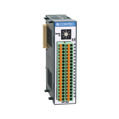
Digital Input F&eIT I/O Module 32ch(Isolated 12 - 24VDC)
This product is an expansion module (device module) that adds digital signal I/O interfaces to one of various types of controllers. The product is used in combination with the I/O controller module < CPU-CAxx(FIT)GY > (*1) or BOX-PC < BX-300-DC5xxx > (*1) or microcontroller unit < CPU-SBxx(FIT)GY > (*1) in the F&eIT Series.This product can perform a maximum of 32 points of opto-isolated input per module. (Input: 12 - 24 VDC specified)
*1 This module is available in different product models. "x" in each model number represents a blank or one alphanumeric character. This is applicable to the rest of this document.
DI-32(FIT)GY has 32 channel digital signal input, treating 16 channels as a group and handling two groups per operation.
Input section is ready to accept both the current sinking output and current source output.
Isolated I/O operations using an opto-coupler improves noise immunity.
It has a digital filter to prevent input signals from carrying noise or a chattering..All of the input signals can be used as interrupt inputs. Interrupt trigger edge of the input signal is also selectable.
A rotary switch allows you to set device IDs to help you keep track of device numbers.
Like other F&eIT series products, the module has a 35mm DIN rail mounting mechanism as standard. A connection to a controller module can be effected on a lateral, stack basis in a unique configuration, which permits a simple, smart system configuration without the need for a backplane board.
Digital Input F&eIT I/O Module 32ch(Isolated 12 - 24VDC)
Model:
DI-32(FIT)GY
Maker:
CONTEC Co., Ltd.
Specifications
Add-on Module
| Series | F&eIT |
|---|---|
| Bus Specification | F&eIT stack bus |
| Size | F&eIT 1U |
| Used Connector | – |
Digital I/O
| Input Channels | 32-ch |
|---|---|
| Output Channels | – |
| Bi-directional I/O Channels | – |
| Response Time (Input) | 1msec (max.) |
| Response Time (Output) | – |
| Operating Voltage (Input) | 12 to 24VDC |
| Operating Voltage (Output) | – |
| Input Circuit | Opto-isolated input (for both current sink and source output) |
| Output Circuit | – |
| Built-in Power Supply | – |
Supported OS
| Supported OS | – |
|---|
*The supported OS depends on connected controllers (CPU-CA20, BX-320 etc.).
System specifications
| Item | Specifications | |
|---|---|---|
| Input section | Input format | Opto-isolated input (compatible with current sink output and current source output) |
| Input resistance | 3kΩ | |
| Input ON current | 3.4 mA or more | |
| Input OFF current | 0.16 mA or less | |
| Number of input signal points | 32 points (16 points/common) | |
| Response time | Within 1msec | |
| External circuit power supply | 12 – 24 VDC (±15%) (4 mA/12V – 8 mA/24V per channel) |
|
| Common section | Interrupt level | Using BX-300-DC5xxx or CPU-SBxx(FIT)GY: IRQ 5, 7, or 9 |
| External circuit power supply | 12 – 24 VDC (±15%) | |
| Internal current consumption | 5 VDC(±5%) 150 mA(Max.) *1 | |
| Allowable distance of signal extension | Approx. 50m (depending on wiring environment) | |
| Physical dimensions (mm) | 25.2(W) x 64.7(D) x 94.0(H) (exclusive of protrusions) | |
| Weight of the module itself | 100g | |
| Module connection method | Stack connection by means of a connection mechanism standard with the system | |
| Module installation method | One-touch connection to 35mm DIN rails (standard connection mechanism provided in the system) |
|
| Applicable wire | AWG24 – 16 | |
| Applicable plug | FMC 1,5/18-ST-3,5(made by Phoenix Contact Corp.) | |
*1 The stack connector accepts currents of up to 3.0A (Max.).
Related Article

To view the pdf files, the Adobe Reader from Adobe Systems is required.