

This website uses cookies so that we can provide you with the best user experience possible. Cookie information is stored in your browser and performs functions such as recognising you when you return to our website and helping our team to understand which sections of the website you find most interesting and useful.


ITEMLIST
Products Infomation

- Products by Category
- RION Normal incidence acoustic measurement system 9301_9302
Normal incidence sound absorption ratio measurement system by 2-microphone method
Model 9302
Nomal incidence Sound absorption raito measurement system
Model 9301
Normal incidence Sound absorption ratio / Sound transmission loss measurement system
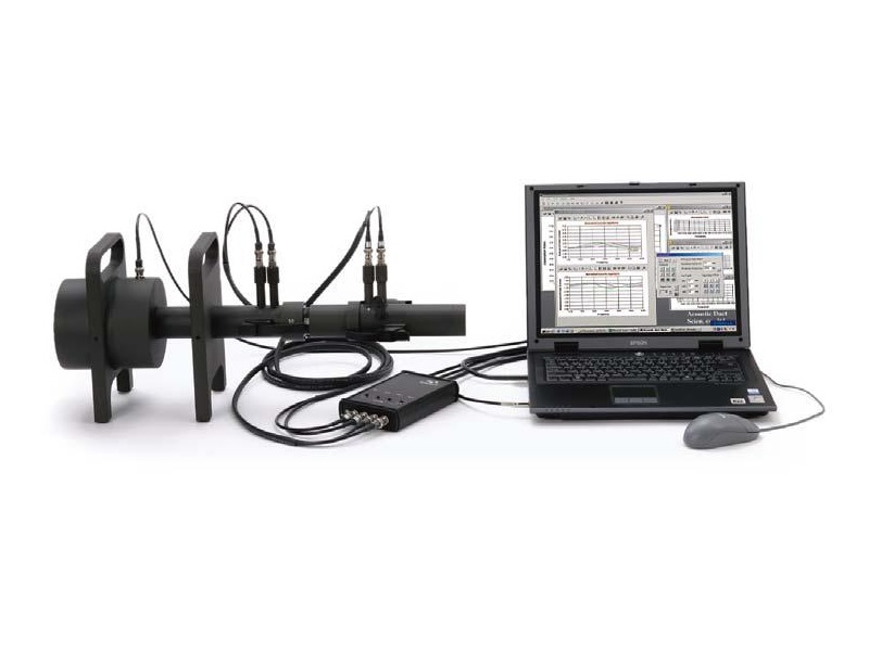
This normal incidence acoustic measurement system captures reflected sound or transmitted sound produced by a source sound hitting a sound absorption material or sound insulation material normally. This is used to measure the sound absorption ratio, acoustic impedance, and related values, as well as the sound during development or review of a material. The system measuring the sound absorption ratio is suitable for measurement of small-size test specimen with a diameter of up to 100mm (108 mm when measuring the sound transmission loss). sound insulation materials for automobiles or buildings, being able to quickly evaluate new materials or laminated materials is a crucial requirement during the development stage. The current system makes it easy to perform such evaluations by determining the physical characteristics of the material.
Normal incidence acoustic measurement system
Model:
9301_9302
Maker:
RION CO.,LTD.
Features
Model 9302 Normal incidence sound absorption ratio measurement system
Determines sound absorption ratio and acoustic impedance related values
of sound absorption material (compliant with JIS A 1405-2 and ISO 10534-2)
- Compliant with JIS A 1405-2, ISO 10534-2:1998 (Determination of Sound absorption ratio And Impedance In Impedance Tubes — Part 2: Transfer-function Method)
- Transfer function method (2-microphone method) allows instantaneous measurement of sound absorption ratio, reflection coefficient, and surface acoustic impedance
- Transfer function method (2-microphone method) allows instantaneous measurement of surface acoustic impedance, characteristic impedance, propagation constant, equivalent sound speed, and equivalent density. Measurement results are used as input data for transfer matrix method prediction software.
- Optional transfer matrix method prediction software allows prediction of sound absorption ratio and sound transmission loss for layered materials (up to 5 layers)
Model 9301 Normal incidence sound absorption ratio / Sound transmission loss measurement system
Measures sound absorption ratio and acoustic impedance related values of sound absorption material and normal incidence sound transmission loss of sound insulation material
- Includes all functions of the Model 9302 for sound absorption ratio measurement(See information on Model 9320. Calibration tube is also used for sound transmission loss measurement.)
- Supports instantaneous measurement of sound transmission loss with 4-microphone method
- If sound transmission loss curve comprises resonance characteristics, normal incidence transmission loss estimation software (Option) can be used to estimate the mass law curve
Specifications
Tube Model 9302 Sound absorption ratio measurement System
Standard compliance JIS A 1405-2, ISO 10534-2:1998
| Tube name | Dia. (mm) | Length (mm) | |
| Low frequency measurement range 1/3 oct (125 Hz to 1600 Hz) |
Main section | 100 | 645 (620)* |
| Calibration section | 100 | 215 | |
| Measurement section | 100 | 210 to 313 | |
| High frequency measurement range 1/3 oct (500 Hz to 6300 Hz) |
Main section | 29 | 345 (320)* |
| Calibration section | 29 | 215 | |
| Measurement section | 29 | 210 to 313 |
*Linked length
- Main tube comprises integrated speakers
- Calibration tube comprises internal sound absorption material
- Two dummy microphones (plastic) supplied
- Test specimen diameter: 100 mm and 29 mm (nominal value)
- Test specimen thickness + back air layer: 100 mm max.
(both for low frequency and high frequency system) - Maximum external dimensions when assembled
Model 9302
For low frequency measurement 280 (H) × 150 (W) × 930 (D) mm
For high frequency measurement 280 (H) × 180 (W) × 640 (D) mm - Test specimen supplied with system: 1 each
Result display (Model 9302)
| Sound absorption ratio | 1/3 octave band analysis, FFT analysis display |
| Acoustic impedance Z | Absolute value, Phase, Real part, Imaginary part |
| Reflection coefficient | Absolute value, Phase, Real part, Imaginary part |
| Surface impedance Z1 | Absolute value, Phase, Real part, Imaginary part |
| Characteristic impedance Zc | Absolute value, Phase, Real part, Imaginary part |
| Propagation constant r | Attenuation constant α, Phase constant β |
| CSV format file output | Density p, Sound velocity c, Z1, Zc , r |
Tube Model 9301* Sound absorption ratio / Sound transmission loss measurement system
*Includes the functions of the normal incidence sound absorption ratio measurement system (Model 9302)
| Tube name | Dia. (mm) | Length (mm) | |
| Low frequency measurement range | Main section | 100 | 645 (620)* |
| Link section | 100 (108) | 96 to 116 | |
| Calibration / Measurement section | 100 | 400 (390)* | |
| Sound absorption ratio measurement section |
100 | 210 | |
| High frequency measurement range | Main section | 29 | 345 (325)* |
| Link section | 29 (36) | 116 to 156 | |
| Calibration / Measurement section | 29 | 169 (159)* | |
| Sound absorption ratio measurement section |
29 | 210 to 313 |
*Linked length
- Main tube comprises integrated speakers
- Calibration / measurement tube comprises internal sound absorption material
- Three dummy microphones (plastic) supplied
- Test specimen diameter: sound absorption ratio measurement 100 mm and 29 mm, sound transmission loss measurement 108 mm and 36 mm (nominal value)
- Sound absorption ratio test specimen thickness + back air layer: 100 mm max. (both for low frequency and high frequency system)
- Maximum external dimensions when assembled
Model 9301
For low frequency measurement 280 (H) × 150 (W) × 1130 (D) mm
For high frequency measurement 280 (H) × 180 (W) × 640 (D) mm - Test specimen supplied with system: 1 each
Result display (Model 9301)
| Sound absorption ratio | 1/3 octave band analysis, FFT analysis display |
| Acoustic impedance Z | Absolute value, Phase, Real part, Imaginary part |
| Reflection coefficient | Absolute value, Phase, Real part, Imaginary part |
| Surface impedance Z1 | Absolute value, Phase, Real part, Imaginary part |
| Characteristic impedance Zc | Absolute value, Phase, Real part, Imaginary part |
| Propagation constant r | Attenuation constant α, Phase constant β |
| CSV format file output | Density p, Sound velocity c, Z1, Zc, r |
| Sound transmission loss | 1/3 octave band analysis, FFT analysis display |
![]()
To view the pdf files, the Adobe Reader from Adobe Systems is required.