




This website uses cookies so that we can provide you with the best user experience possible. Cookie information is stored in your browser and performs functions such as recognising you when you return to our website and helping our team to understand which sections of the website you find most interesting and useful.


Products
The products listed here are for overseas markets, not for Japan domestic.

- Electronic Measuring Instruments
- Power Supplies / Electronic Load Devices
- KIKUSUI Compact Variable-switching Regulated DC Power Supply PAV Series – 800W Model
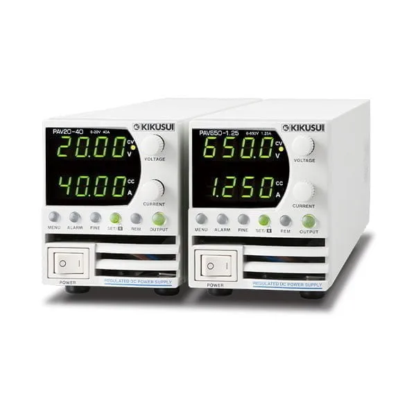
Palm-sized withmaximum power output at 800 W.
The PAV series is a compact, high power density, high performance constant voltage (CV) / constant current (CC) variable switching power supply.
The PAV consists of 64 models total* with 4 types of maximum power outputs
at 200 W, 400 W, 600 W and 800 W and output voltages from 10 V through 650 V.
All models are standardized to a same size with 2U high (approximately 88 mm) and have high power density for bench-top use.
The PAV series allows sequence settings with an embedded CPU as well as analog control.
A harmonic current control circuit is embedded with a power factor of 0.99 to take power environment into account.
* LAN model included (with LAN)
Compact Variable-switching Regulated DC Power Supply PAV Series – 800W Model
Model:
PAV10-72, PAV20-40, PAV36-24, PAV60-14, PAV100-8, PAV160-5, PAV320-2.5, PAV650-1.25
Maker:
KIKUSUI ELECTRONICS CORPORATION
Features
- 2U bench-top type
- Palm-sized, portable power supply
- Output power: 200W/400W/600W/800W 4models
- Output voltage: 10V to 650V 8models
- USB/RS232C/RS485 as standard interface (*LAN is a factory option)
- 64 models total (LAN model included)
Line up
| SKU | Output CV [V] | Output CC [A] | Output Power [W] |
|---|---|---|---|
| PAV10-72 | 10V | 72 | 800W |
| PAV10-72 with LAN | 10V | 72 | 800W |
| PAV20-40 | 20V | 40 | 800W |
| PAV20-40 with LAN | 20V | 40 | 800W |
| PAV36-24 | 36V | 24 | 800W |
| PAV36-24 with LAN | 36V | 24 | 800W |
| PAV60-14 | 60V | 14 | 800W |
| PAV60-14 with LAN | 60V | 14 | 800W |
| PAV100-8 | 100V | 8 | 800W |
| PAV100-8 with LAN | 100V | 8 | 800W |
| PAV160-5 | 160V | 5 | 800W |
| PAV160-5 with LAN | 160V | 5 | 800W |
| PAV320-2.5 | 320V | 2.5 | 800W |
| PAV320-2.5 with LAN | 320V | 2.5 | 800W |
| PAV650-1.25 | 650V | 1.25 | 800W |
| PAV650-1.25 with LAN | 650V | 1.25 | 800W |
Specifications
| 800 W type | PAV10-72 | PAV20-40 | PAV36-24 | PAV60-14 | PAV100-8 | PAV160-5 | PAV320-2.5 | PAV650-1.25 | ||
|---|---|---|---|---|---|---|---|---|---|---|
| Output | ||||||||||
| Rated output voltage *1 | 10 V | 20 V | 36 V | 60 V | 100 V | 160 V | 320 V | 650 V | ||
| Rated output current *2 | 100 Vac ≤ Vin*3 Ta*4 ≤ 50°C |
72 A | 40 A | 24 A | 14 A | 8 A | 5 A | 2.5 A | 1.25 A | |
| Vin < 100 Vac Ta ≤ 40°C |
72 A | 40 A | 24 A | 14 A | 8 A | 5 A | 2.5 A | 1.25 A | ||
| Vin < 100 Vac 40°C < Ta ≤ 50°C |
66 A | 36 A | 20 A | 12.5 A | 7.5 A | 4.7 A | 2.35 A | 1.15 A | ||
| Rated output power | 100 Vac ≤ Vin Ta ≤ 50°C |
720 W | 800 W | 864 W | 840 W | 800 W | 800 W | 800 W | 812.5 W | |
| Vin < 100 Vac Ta ≤ 40°C |
720 W | 800 W | 864 W | 840 W | 800 W | 800 W | 800 W | 812.5 W | ||
| Vin < 100 Vac 40°C < Ta ≤ 50°C |
660 W | 720 W | 720 W | 750 W | 750 W | 752 W | 752 W | 747.5 W | ||
| AC input | ||||||||||
| AC input | Nominal input rating | 100 Vac to 240 Vac continuous input, 50 Hz to 60 Hz, single phase | ||||||||
| Input voltage range | 85 Vac to 265 Vac | |||||||||
| Input frequency range | 47 Hz to 63 Hz | |||||||||
| Input current (typ) *5 (100 Vac/200 Vac) | 9.00 A / 4.45 A | 9.65 A / 4.75 A | 10.30 A / 5.10 A | 10.00 A / 4.95 A | 9.50 A / 4.70 A | 9.34 A / 4.61 A | 9.34 A / 4.59 A | 9.43 A / 4.66 A | ||
| Power factor (typ) (100 Vac/200 Vac, at the rated output power) | 0.99 / 0.98 | |||||||||
| Efficiency (typ) *5 | 81% / 83% | 84% / 86% | 85% / 87% | 85% / 87% | 85% / 87% | 86.5% / 88.5% | 86.5% / 89% | 87% / 89% | ||
| Inrush current(100 Vac/200 Vac) *6 | 30 A / 30 A or less | |||||||||
| Constant voltage mode | ||||||||||
| Maximum line regulation *7 (for the rated output voltage) | 0.01% + 2 mV | 0.01% | ||||||||
| Maximum load regulation *8 (for the rated output voltage) | ||||||||||
| Ripple noise *9 | 20 MHz, p-p | 50 mV | 50 mV | 50 mV | 60 mV | 80 mV | 100 mV | 150 mV | 250 mV | |
| 5 Hz to 1 MHz, rms | 5 mV | 5 mV | 5 mV | 12 mV | 15 mV | 10 mV | 30 mV | 60 mV | ||
| Temperature coefficient | 30 PPM /°C (after a 30 minute warm-up, for the rated output voltage) | |||||||||
| Aging drift *10 (for the rated output voltage) | 0.05% | 0.02% | ||||||||
| Initial drift *11 (for the rated output voltage) | 0.05% + 2 mV | 0.05% | ||||||||
| Maximum remote sensing compensation voltage (single line (positive or negative)) | 1 V | 1 V | 2 V | 3 V | 5 V | 5 V | ||||
| Rise time *12 | 50 ms | 50 ms | 50 ms | 50 ms | 100 ms | 45 ms | 55 ms | 55 ms | ||
| Fall time | At full load *12 | 25 ms | 25 ms | 25 ms | 25 ms | 80 ms | 55 ms | 65 ms | 65 ms | |
| Td (typ) *13 | 285 ms | 425 ms | 450 ms | 570 ms | 1370 ms | — | ||||
| No load a *14 | 65 ms | 110 ms | 155 ms | 175 ms | 375 ms | — | ||||
| No load b *15 | 280 ms | 470 ms | 470 ms | 500 ms | 1200 ms | 2000 ms | 2500 ms | 3000 ms | ||
| Transient response time *16 | 1 ms or less | 2 ms or less | ||||||||
| Output hold time (typ) *17 | 10 ms | 13 ms | 11.5 ms | |||||||
| Constant current mode | ||||||||||
| Maximum line regulation *7 (at the rated output current) | 0.01% + 2 mA | 0.02% | ||||||||
| Maximum load regulation *18 (at the rated output current) | 0.01% + 5 mA | 0.09% | 0.15% | |||||||
| Change in the load due to the temperature drift of internal components (at the rated output current) | 0.15% or less | 0.1% or less | 0.05% or less | |||||||
| (for 30 minutes after the load conditions are changed) | ||||||||||
| Ripple noise *19 (5 Hz to 1 MHz, rms) | 180 mA | 100 mA | 31 mA | 28 mA | 12 mA | 2 mA | 1.5 mA | 1 mA | ||
| Temperature coefficient | 100 PPM /°C (after a 30 minute warm-up, at the rated output current) | |||||||||
| Aging drift *8 (at the rated output current) | 0.05% | |||||||||
| Initial drift *9 (at the rated output current) | 0.3% | 0.1% | ||||||||
| Protection functions | ||||||||||
| Foldback protection | Turns off the output when the operation switches from constant voltage mode to constant current mode or vice versa. Can be set as necessary. | |||||||||
| Overvoltage protection (OVP) | Inverter shutoff system. Prevents the output voltage from being set higher than the OVP value. Also shuts off the output when an output overvoltage (exceeding the OVP value) occurs. | |||||||||
| Overvoltage protection voltage setting range | 0.5 V to 12 V | 1 V to 24 V | 2 V to 40 V | 5 V to 66 V | 5 V to 110 V | 5 V to 176 V | 5 V to 353 V | 5 V to 717 V | ||
| Undervoltage limit (UVL) | Prevents the output voltage from being set lower than the UVL value. Disabled during external control. | |||||||||
| Undervoltage protection (UVP) | Shuts off the output when the output voltage falls below the UVP value. | |||||||||
| Overheat protection | Shuts off the output before the temperature of the internal components exceeds the safe operation temperature. | |||||||||
| Setting and readback (USB, RS232, RS485, optional LAN interface) | ||||||||||
| Output voltage setting | Accuracy | 0.05% of the rated output voltage | 0.05% of the output voltage + 0.05% of the rated output voltage | |||||||
| Number of decimal digits | 3 digits | 2 digits | ||||||||
| Resolution | Approx. 1/60000 of rated output voltage | |||||||||
| Output current setting | Accuracy *20 | 0.1% of output current + 0.1% of the rated output current | 0.2% of the rated output current | |||||||
| Number of decimal digits | 2 digits | 3 digits | 4 digits | |||||||
| Resolution | Approx. 1/60000 of rated output current | |||||||||
| Output voltage readback | Accuracy | 0.05% of the rated output voltage | 0.05% of the output voltage + 0.05% of the rated output voltage | |||||||
| Resolution | Approx. 1/60000 of rated output voltage | |||||||||
| Output current readback | Accuracy *20 | 0.1% of output current + 0.3% of the rated output current | ||||||||
| Resolution | Approx. 1/60000 of rated output current | |||||||||
| Front panel | ||||||||||
| Control function | ● Separate knobs (encoders) for setting the output voltage and output current (setting resolution switchable). ● Knobs (encoders) for setting OVP, UVP, and UVL. ● Protection functions (OVP, UVP, UVL, foldback) ● Output shutoff function (output on/off control, shutdown) ● Communication functions: Standard equipped with USB, RS232, RS485. LAN optional. ● Baudrate, address setting ● External control: Configuration using external voltage (5 V or 10 V) or external resistance (5 kΩ or 10 kΩ), output voltage/current monitor output (5 V or 10 V), output on/off, front panel operation lock |
|||||||||
| Output voltage display<\th> | Accuracy | 0.5% of the rated output voltage ± 1 count | ||||||||
| Number of decimal digits | 2 digits | 1 digit | ||||||||
| Output current display<\th> | Accuracy | 0.5% of the rated output current ± 1 count | ||||||||
| Number of decimal digits | 2 digits | 3 digits | ||||||||
| LED display | Green: FINE, MENU, SET, ALARM, REM, OUTPUT, CV, CC Red: ALARM (OVP, UVP, OTP, FOLD, AC FAIL) |
|||||||||
| Setting keys | FINE, MENU, SET, ALARM, REM, OUTPUT | |||||||||
*1. The minimum voltage is 0.1% the rated output voltage.
*2. The minimum current is 0.2% of the rated output current.
*3. Vin: Input voltage
*4. Ta: Ambient temperature (performance depending on the input voltage versus rated output current and ambient temperature shown below)
*5. Input voltage 100 Vac/200 Vac, at the rated output power, ambient temperature 25 °C If the LAN option is built in, the efficiency decreases by 0.5% and the input current increases by 0.5%.
*6. Excludes input surge current (duration 0.2 ms or less) applied to the built-in noise filter section.
*7. 85 Vac to 132 Vac or 170 Vac to 265 Vac, fixed load
*8. With the input voltage held constant, the sensing point was measured using remote sensing from no load to full load.
*9. Models with rated output voltages from 10 V to 100 V were measured using an RC-9131 A 1:1 probe that conforms to the JEITA specifications. Models with rated output voltage from 160 V to 650 V were measured using a 10:1 probe. At an ambient temperature of 0 °C, measurement was performed after at least 1 minute had passed after startup.
*10. When at least 8 hours has passed after a 30 minute warm-up with the input voltage, load, and ambient temperature held constant
*11. For 30 minutes after turning on the power with the input voltage, load, and ambient temperature held constant
*12. Between 10% and 90% of the rated resistive load and rated output voltage
*13. If the output voltage is repeatedly decreased, Td is the minimum duration from a given voltage drop to the next voltage drop.
*14. Duration for the voltage to change from 90% to 10% of the rated output voltage when the output voltage is repeatedly decreased and the duration from a given voltage drop to the next voltage drop is longer than Td.
*15. Duration for the voltage to change from 90% to 10% of the rated output voltage when the output voltage is repeatedly decreased and the duration from a given voltage drop to the next voltage drop is shorter than Td.
*16. The amount of time required for the output voltage to return to a value within 0.5% of the rated output voltage. The change in the load current is 10% to 90% of the rating. The output voltage is between 10% and 100% of the rating. During local sensing.
*17. At the rated output power
*18. The value when the output voltage is changed from the lower limit to the rated voltage in constant current mode with the input voltage held constant
*19. For models with a 10 V rated output voltage, this is the value for when the output voltage is 2 V to 10 V at the rated output current. For other models, this is the value for when the output voltage is 10 % to 100 % of the rating at the rated output current. Models with rated output voltage from 160 V to 650 V were measured using a 10:1 probe.
*20. In output current control, the current, linearity, and monitor accuracies do not include the load variation caused by initial drift and temperature drift of internal components.
Related Article

To view the pdf files, the Adobe Reader from Adobe Systems is required.