



This website uses cookies so that we can provide you with the best user experience possible. Cookie information is stored in your browser and performs functions such as recognising you when you return to our website and helping our team to understand which sections of the website you find most interesting and useful.


Products
The products listed here are for overseas markets, not for Japan domestic.

- Electronic Measuring Instruments
- Electrical Safety Testers / Measuring Instruments
- MICROTEST Power Tester 7130
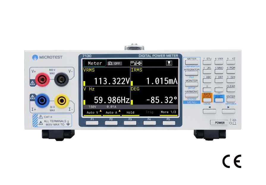
Supports Three Major Graphical Analysis Functions (Trend , Bar Chart, Waveform ). ±0.05% Ultra High Accuracy, Auto Integration up to 10,000 Hours with 100th Harmonic Analysis Unveiling Power′s Secrets.
The MICROTEST 7130 is designed for single-phase AC/DC power measurement, featuring a 0.2Hz–100kHz bandwidth, 500kSPS sampling rate, and ±0.05% accuracy in a compact design with a 4.3” TFT LCD. It supports 800V/30A direct input, 50th-order harmonic analysis, and simultaneous harmonic and integration measurements. The built-in graphical display and basic oscilloscope function allow real-time voltage and current waveform observation. USB Host enables direct waveform capture and data logging—no external oscilloscope needed. For standby power testing, it offers a 5mA range, 10μW resolution, and Meter mode displays 4, 8, or 16 parameters with real-time min/max tracking. Comparison mode provides PASS/FAIL evaluation, optimizing R&D, production, and quality control.
Power Meter
Model:
7130
Maker:
MICROTEST Corporation
Features
- Ultra-High Measurement Accuracy ±0.05%
- 50th-Order Harmonic Analysis
- High-Speed 500kSPS Sampling Rate
- Simultaneous AC+DC Measurement and Display
- Rated Direct Input Voltage: 800V / Input Current: 30A
- DC, 0.2Hz~100kHz Voltage/Current Measurement Bandwidth
- 4.3” Color Multifunctional Digital & Graphical LCD Display
- Supports voltage and current waveform analysis mode
- Automatic Integration up to 10,000 Hours with Simultaneous Harmonic Analysis
- Minimum Current Range of 5mA & Power Resolution of 10μW
- Supports Comparison Mode with Upper/Lower Limit PASS/FAIL Judgment
Line up
| Model | 7140 Power Analyzer | 7130 Power Meter |
| Frequency Range | DC, 0.2Hz~100kHz | DC, 0.2Hz~100kHz |
| Basic Measurement Accuracy | ±0.05% | ±0.05% |
| Sampling Rate | 500kSPS | 500kSPS |
| Meter Mode | ● | ● |
| Harmonic Analysis | 100th-order harmonic | 50th-order harmonic |
| Voltage and Current Waveform Display | ● | ● |
| Power Trend Graph | ● | – |
| Harmonic Bar Chart | ● | – |
MICROTEST 7140 Power Analyzer
Specifications
Input
| Measurement range |
Voltage |
Crest factor 3: 15V/ 30V/ 60V/ 150V/ 300V/ 600V | |
| Crest factor 6: 7.5V/ 15V/ 30V/ 75V/ 150V/ 300V | |||
| Current: Direct input | Crest factor 3: 5mA/10mA/20mA/50mA/100mA/200mA/0.5A/1A/2A/5A/10A/20A(Max30A) Crest factor 6: 2.5mA/5mA/10mA/25mA/50mA/100mA/0.25A/0.5A/1A/2.5A/5A/10A |
||
| Current External current sensor input |
Crest factor 3: 500mV/ 1V/ 2V/ 5V/ 10V | ||
| Input impedance | Voltage | Input resistance: Approx. 1.66MΩ Input capacitance:Approx. 13pF (Parallel with the resistance) |
|
| Current Direct input |
Crest factor 3: 5mA/10mA/20mA/50mA/100mA/200mA Crest factor 6: 2.5mA/5mA/10mA/25mA/50mA/100mA |
Input resistance:Approx. 500mΩ+10mΩ(wire) Input inductance:Approx. 0.1μH |
|
| Crest factor 3: 0.5A/1A/2A/5A/10A/20A Crest factor 6: 0.25A/0.5A/1A/2.5A/5A/10A |
Input resistance: Approx. 5mΩ + 3mΩ(wire) Input inductance: Approx. 0.1μH |
||
| Current External current sensor input |
Crest factor 3: 0.5V/1V/2V/5V/10V | Input resistance: Approx. 10kΩ | |
| Continuous maximum allowable input |
BNC | Max AC 10V | |
| Voltage | Peak value 1131V | ||
| Current | Crest factor 3: 5mA/10mA/20mA/50mA/100mA/200mA Crest factor 6: 2.5mA/5mA/10mA/25mA/50mA/100mA |
Maximum current: 0.9A | |
| Crest factor 3: 0.5A/1A/2A/5A/10A/20A Crest factor 6: 0.25A/0.5A/1A/2.5A/5A/10A |
Maximum current: 30A | ||
| Line filter | Select OFF or ON(cutoff frequency at 500Hz/5kHz/100kHz), THD ON(cutoff frequency at 500Hz/ 5kHz) | ||
| Frequency filter | Select OFF or ON(cutoff frequency at 500Hz) | ||
| A/D converter | Simultaneous conversion of voltage and current inputs Resolution: 16bits, Maximum conversion rate: 500kSPS |
||
Voltage/ Current/ Active Power Accuracy
| Voltage and Current Accuracy |
Accuracy | DC | DC Accuracy ±0.05% reading ± 0.05% of range |
| 0.2Hz ≦ f < 45Hz | ±(0.1% of reading + 0.1% of range) | ||
| 45Hz ≦ f ≦ 66Hz | ±(0.05% of reading + 0.05% of range) | ||
| 66Hz < f ≦ 1kHz | (0.1% of reading + 0.1 % of range) | ||
| 1kHz < f ≦ 10kHz | ±([{0.07×(f)}% of reading] + 0.3% of range ) | ||
| 10kHz < f ≦ 100kHz | ±(0.4 % of reading + 0.4 % of range)±[{0.04×(f–10)}% of reading] | ||
| Frequency range |
Data update interval | Measurement Frequency Range | |
| 0.05s | 40Hz ~ 100kHz | ||
| 0.1s | 20Hz ~ 100kHz | ||
| 0.2s | 10Hz ~ 100kHz | ||
| 0.25s | 8Hz ~ 100kHz | ||
| 0.5s | 5Hz ~ 100kHz | ||
| 1s | 2Hz ~ 100kHz | ||
| 2s | 1.5Hz ~ 100kHz | ||
| 5s | 0.5Hz ~ 100kHz | ||
| 10s~60mins | 0.2Hz ~ 100kHz | ||
|
Active Power Accuracy |
Requirements | Same as the conditions for voltage and current. Power factor: 1 | |
| Accuracy | DC | ±(0.05% reading ± 0.05% of range) | |
| 0.1Hz ≦ f < 45Hz | ±(0.2% of reading + 0.2% of range) | ||
| 45Hz ≦ f ≦ 66Hz | ±(0.05% of reading + 0.05% of range) | ||
| 66Hz <f ≦ 1kHz | ±(0.1% of reading + 0.1 % of range) | ||
| 1kHz <f ≦ 10kHz | ±(0.1% of reading + 0.2% of range)± [{0.06×(f)}% of reading] | ||
| 10kHz < f ≦ 100kHz | ±(0.4 % of reading + 0.4 % of range)±[{0.07×(f–10)}% of reading] | ||
Integration
| Mode | Manual integration mode |
|---|---|
| Timer | Automatically stop integration by setting a timer Selectable range: 0h00m00s ~ 9999h59m59s(0h00m00s, automatically sets to manual integration mode) |
| Count overflow | WP: 999999MWh/-99999MWh, q: 999999MAh/-99999MAh |
| Accuracy |
±(Power accuracy (or current accuracy) + 0.05% of reading) (fixed range) * In auto-range mode, measurement is not performed during range switching. The first measurement after switching and the non-measurement period are included in calculations |
| Range setting |
Auto range or fixed range for Integration is available. * Refer to the “Voltage, Current, and Power Measurement” section for range switching. |
| Valid Frequency Ranges for Integration |
Active power: DC to 100 kHz Current: DC to 100 kHz |
| Timer accuracy | ±0.02% |
Harmonic
| Measured item | 1~100 {Voltage, Current, Power, Voltage Ratio, Current Ratio, Power Ratio, Voltage Phase Angle, Current Phase Angle}, and all measurement items when THD is not enabled | ||
|---|---|---|---|
| Method | PLL synchronization method with Discrete Fourier Transform for harmonic analysis | ||
| Frequency range | Fundamental frequency of the PLL source is in the range of 20Hz ~ 480Hz | ||
| PLL source | Select voltage or current of each input element | ||
| DFT data length | 4096 | ||
| Accuracy | 20Hz ≦ f < 45Hz | ±(0.2% of reading + 0.2% of range) | |
| 45Hz ≦ f ≦ 66Hz | ±(0.05% of reading + 0.05% of range) | ||
| 66Hz < f ≦ 1kHz | ±(0.1% of reading + 0.1 % of range) | ||
| 1kHz < f ≦ 10kHz | ±(0.1% of reading + 0.2% of range)± [{0.06×(f)}% of reading] | ||
| 10kHz < f ≦ 48kHz | ±(0.4 % of reading + 0.4 % of range)±[{0.07×(f–10)}% of reading] | ||
System
| Supply voltage | 100VAC~240VAC, 50~60 Hz |
|---|---|
| Power consumption | 30VA MAX |
| Display | 4.3″TFT, 800*480 |
| Remote Control Input/Output Signal | USB、RS-232、ETHERNET 10/100M |
| Memory | USB disk、Embed flash |
| Operating environment | Temperature: 13°C to 40°C Humidity: < 80%RH |
| Weight | 2.9kg |
| Dimensions | 214x115x300mm |

To view the pdf files, the Adobe Reader from Adobe Systems is required.