




This website uses cookies so that we can provide you with the best user experience possible. Cookie information is stored in your browser and performs functions such as recognising you when you return to our website and helping our team to understand which sections of the website you find most interesting and useful.


Products
The products listed here are for overseas markets, not for Japan domestic.

- Electronic Measuring Instruments
- Electrical Safety Testers / Measuring Instruments
- MICROTEST Impulse Winding Tester 7750 Series
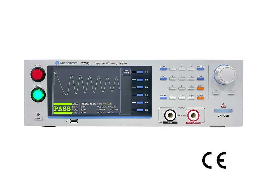
Provide reliable insulation quality testing for both high and low inductance wound components.
MICROTEST 7750 is an advanced Impulse Winding Tester with a faster color display screen. It provides pulse voltage outputs of 1200V/5200V/10000V and utilizes high-speed sampling technology at 200MHz/9 bits. It offers various comparison modes such as total area, area difference, corona count, jitter count, second-order differentiation, and waveform comparison. With a testing speed of up to 10 times per second, it is ideal for high-speed production lines.
For testing small components, the optional 7750-1 tester comes with the FX-IM0001 four-wire SMD component testing fixture. It features voltage compensation to minimize voltage errors caused by wiring and equivalent inductance, ensuring accurate quality control for products with small inductance.
Impulse Winding Tester 7750 Series
Model:
7750-1S, 7750-1F, 7750-5E, 7750-5H, 7750-5S, 7759, 7750-10S
Maker:
MICROTEST Corporation
Features
- Lowest Inductance (≥0.1μH)
- High voltage calibration
- programmable impulse voltage
- 200MHz/9bit High Impulse Test Sampling Rate
- Total Area Comparison
- Differential Area Comparison
- Corona Comparison
- LAPLACIAN Comparison
- Voltage Compensation Function
7750 Impulse Winding Tester
Specifications
| Model | 7750-1S | 7750-1F | 7750-5E | 7750-5H | 7750-5S | 7759 | 7750-10S |
| Channel | 1 | 1 | 1 | 1 | 1 | 9 | 1 |
| Sampling Rate | 200MHz/ 9bit | 200MHz/ 9bit | 50MHz/ 9bit | 100MHz/ 9bit | 200MHz/ 9bit | 200MHz/ 9bit | 200MHz/ 9bit |
| Voltage Output | 10V-1200V | 100V-5200V | 200V-10000V | ||||
| Lowest Inductance | ≥ 0.1μH | ≥ 0.1μH | ≥ 16μH | ≥ 4μH | ≥ 1μH | ≥ 1μH | ≥ 20μH |
| Test Time | 10 times/ Sec | ||||||
| Breakdown Voltage Test | ● | ● | – | – | ● | ● | ● |
| LAN Interface | ● | ● | – | – | ● | ● | ● |
| Waveform Analysis | |||||||
| Total area comparison | ● | ● | ● | ● | ● | ● | ● |
| Differential area comparison | ● | ● | ● | ● | ● | ● | ● |
| LAPLACIAN Comparison | ● | ● | – | ● | ● | ● | ● |
| Corona comparison | ● | ● | ● | ● | ● | ● | ● |
| FLUT Comparison | ● | ● | ● | ● | ● | ● | ● |
| COMP Comparison | ● | ● | ● | ● | ● | ● | ● |
SPEC
| Pulse Number | Max. 32 | |
| Input Impedance | 20MΩ | |
| Measurement Statistics | ● | |
| Provides 6 waveform comparison | ||
| Total area comparison |
When layer short happened, the loss of power on coil increase, the resonance damping coefficient increase, resonance amplitude decrease, the total area decrease. These are the basic parameters we check layer short. By calculating and comparing the deference of area between golden sample and DUT. Show by percentage Analysis the power loss by this data. |
|
| Differential area comparison |
Add up the difference between normal wave and DUT wave call “ Area differential”. When layer short happened, the inductance reduce(similar the transformer). The wave phase change and the area differential also change. This will show “fail” on the instrument. However, the parameter might cause deviation because of the deviation of inductance, resonance phase shift. (Silicon steel product such as motor and traditional transformer is not suitable) By calculating and comparing the deference of area between golden sample and DUT. To determine the degree of waveform overlap. Compare the inductance by this. |
|
| Corona comparison |
In pulse test, the insulation defect will cause discharge and create corona. This function is able to count the times that corona happened base on the degree of deviation. Detect the discharge phenomenon on the coil. |
|
|
LAPLACIAN Comparison |
Poor insulation quality of the coil results in discharge under high voltage impact, causing rapid changes in the oscillation waveform. By employing the 7750 second-order differentiation algorithm, the maximum discharge capacity is obtained, effectively detecting quality issues related to electrical leakage caused by poor solder joints in the monolithic inductor. |
|
|
COMP Comparison |
By setting an allowable waveform range for the standard wave, this feature can simultaneously determine the amplitude and phase of the resonant wave. It enhances the detection capability of inter-turn short circuits. |
|
|
FLUT Comparison |
When there is inter-turn discharge in the winding coil, the waveform will exhibit tremors or fluctuations. Therefore, the instrument quantifies the degree of waveform tremors into numerical values for comparison. |
|
SYSTEM
| PLC Remote Control | Test、About |
| PLC Remote Output Signal | PASS、FAIL、HV Output、Testing |
| Built-in Storage | 200 sets testing waveform |
| Power Supply | Voltage:98Vac-132Vac 或192Vac-264Vac |
| Frequency:50/60Hz ±5% | |
| Power consumption | 70VA |
| Environment | Temperature:10℃-40℃ |
| Humidity:20-80%RH | |
| Dimension | 430x132x370 mm (W*H*D) |
| Weight | 7Kg |
| Interface |
USB Host/Device、RS-232、Remote、LAN GPIB (Option) |
| Display | 7″ dot-matrix (800*480 ) |
Related Article

To view the pdf files, the Adobe Reader from Adobe Systems is required.