




This website uses cookies so that we can provide you with the best user experience possible. Cookie information is stored in your browser and performs functions such as recognising you when you return to our website and helping our team to understand which sections of the website you find most interesting and useful.


Products
The products listed here are for overseas markets, not for Japan domestic.

- Information Equipment / Software
- Industrial PC
- CONTEC Raspberry Pi Industrial Small Embedded Card CPI-MS10CM4
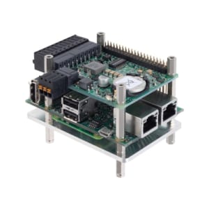
Highly compatible with Raspberry Pi 4 - Industrial grade product with Raspberry Pi OS pre-installed - Get start now and running quickly
The CPI-MS10CM4 is our original board computer based on the Raspberry Pi embedded module Compute Module 4 (CM4). By utilizing the vast peripheral assets for Raspberry Pi, including our "CPI series," you can build a variety of applications.
Raspberry Pi Industrial small embedded card
Model:
CPI-MS10CM4
Maker:
CONTEC Co., Ltd.
Features
- Highly compatible with Raspberry Pi 4 – Industrial grade product with improved reliability and environmental resistance
Uses Raspberry Pi Compute Module 4 (CM4). High compatibility with Raspberry Pi is ensured. Wide temperature range design for use: -20 to 60°C (-4 to 140°F) (airflow 0.7ms). Equipped with our RTC/RAS card for Raspberry Pi (CPI-RAS), watchdog timer (WDT) and clock (RTC). Equipped with a high-output, high-efficiency power supply circuit and noise filter for the power supply, generating clean 5VDC to supply to the internal circuitry. - Raspberry Pi OS pre-installed – Get start now and running quickly
The Raspberry Pi OS is pre-installed. You can start using it right away. Utilize Pi peripheral assets. Compatible with our CPI series of measurement control cards, a pioneer in PC-based measurement control, and expand the I/O required for FA control systems, such as digital I/O, analog I/O, and counters, up to 8 cards via local bus (I2C). - HAT-sized card for I/O expansion – Make full use of your Raspberry Pi peripheral assets
Equipped with a HAT 40-pin header GPIO, it utilizes the peripheral assets of Raspberry Pi. Compatible with our CPI series of measurement control cards, a pioneer in PC-based measurement control, it can expand the I/O required for FA control systems, such as digital I/O, analog I/O, and counters, up to 8 cards via local bus (I2C).
Specifications
| Item | Description | |
|---|---|---|
| CM4 Module | Module | Raspberry Pi Compute Module 4 |
| CPU | Broadcom BCM2711 quad-core Cortex-A72 (ARM v8) 64-bit SoC @ 1.5GHz | |
| GPU | VideoCore VI® 500MHz | |
| Memory | 2GB LPDDR4-3200 SDRAM | |
| eMMC storage | 16GB eMMC Flash (100MB/s) | |
| Interface | Image output | HDMI1.4×1 (Set the resolution to 1920 × 1080 or lower.) |
| USB | USB2.0 Type A×2, USB2.0 Micro-B×1 (used to write the OS) | |
| LAN | 1000BASE-T/100BASE-TX/10BASE-T×1 (built-in CM4 module×1), 100BASE-TX/10BASE-T×1 (MICROCHIP LAN9512×1) |
|
| NVMe | PCIe Gen2 type2242 Key-M | |
| LED | Power LED, Status LED, Access LED, Active LED | |
| Switch | Power switch, Setting switch | |
| Digital Input | Input type | Non-isolated opto-coupler input (supports current sink output [negative logic] *1) |
| Number of input signal channels | 2 | |
| Isolation | Non-isolated | |
| Voltage Resistance | Non-isolated | |
| Internal power supply | 3.3V±5% | |
| Input Resistance | Current-limiting: 220Ω, Shunt resistance: 1kΩ | |
| Input ON current | 6.4mA (Typ) | |
| Input OFF current | 0.16mA or less | |
| Input signal voltage | 3.3 – 28VDC | |
| Digital Output | Output type | Solid State Relay output |
| Number of output signal channels | 1 | |
| Isolation | Solid State Relay isolation | |
| Voltage Resistance | AC1000Vrms | |
| Output rating (Output Voltage) | 28VAC/DC (Max.) | |
| Output rating (Output Current) | 200mA (Max.) | |
| ON resistance | 2Ω or less (25°C) | |
| OFF leak current | 1μA or less (25°C) | |
| External power supply output | 8 – 28VDC power supply output | Max. 2A (Output voltage varies according to DC power supply input voltage) |
| 5VDC power supply output | <No additional expansion card, 5VDC bus partial power output 0A, USB device 1.0A supply, SSD installed>5V±5% 500mA (Max.) *2 | |
| DIO Connector | 2 pieces 3.81mm pitch 10-pin terminal | |
| Compatible DIO Connector wire | AWG26 – 16 | |
| Bus specification | Power supply output | <No additional expansion card, 5VDC bus partial power output 0A, USB device 1.0A supply, SSD installed> 5V±5% 500mA (Max.) *2 3.3V±5% 500mA (Max.) |
| I2C bus (I2C1) | Used for 0x2c address and 0x32 address | |
| Interrupt notification | Function | Open collector output (Pull-up: 15kΩ) |
| Notification destination | Select from GPIO 4, 5, 6, or 22 (using DIP switch) | |
| Power supply | Rated input voltage | 8 – 28VDC |
| Input voltage range | 6 – 30VDC | |
| Consumption power *3 | <8VDC 4.0A (Max.), 28VDC 1.1A (Max.) <8V to 28V and with an external power supply output of 0A> 8VDC 4.0A(Max.) 28VDC 1.1A(Max.) |
|
| Connector | 2 pieces 3.5mm pitch 3-pin terminal (V+, V-, FG) | |
| Applicable wire | AWG22 – 16 | |
| Physical dimensions | 82.9(W)×56.5(D)×61.7(H) mm | |
| Weight | 200g (approx.) | |
*1 Data “0” and “1” correspond to the High and Low levels, respectively.
*2 The power supply output value should be such that the total power consumption value is less than the available power supply value. For details, refer to “About current consumption of Expansion Cards and External Power Contribution”.
*3 The product is equipped with a fuse (rated current: 5A) for preventing overcurrent in the power supply input. Use a power supply that has overcurrent protection or that has a current capacity capable of blowing the fuse (9.5A or more is recommended). When using a power supply of 17V or less, the current value of the power input section should be 4A or less.
Related Article

To view the pdf files, the Adobe Reader from Adobe Systems is required.