This website uses cookies so that we can provide you with the best user experience possible. Cookie information is stored in your browser and performs functions such as recognising you when you return to our website and helping our team to understand which sections of the website you find most interesting and useful.

ITEMLIST
Products Infomation

- Products by Category
- Electronic Measuring Instruments
- Power Supplies / Electronic Load Devices
- KIKUSUI PMX-Multi Series
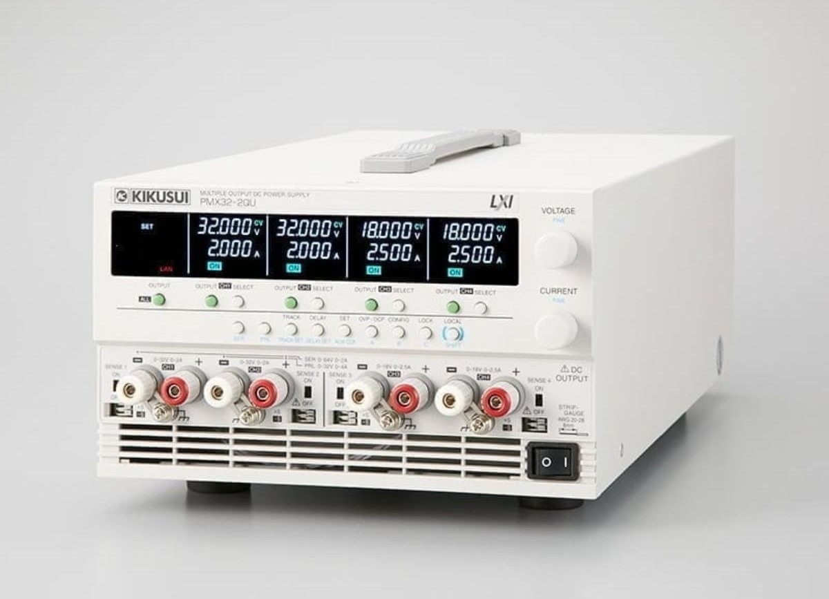
Compact Multi-Output DC Power Supply

Request a Quote
The Kikusui PMX-Multi Series is a compact, multi-output DC power supply available in 2, 3, or 4-channel models with isolated outputs.
Each channel offers high-resolution settings (1 mV/0.1 mA), tracking control, and flexible ON/OFF delay.
Simple series/parallel connections expand test versatility. Equipped with LAN (LXI compliant), USB, and RS232C interfaces, it supports seamless integration into automated systems.
With robust protections, key lock, preset memories, and a high-visibility LCD, the PMX-Multi Series delivers precision, safety, and efficiency for advanced R&D and production testing.
Features
- Three models with 2, 3 and 4 outputs
- Each output is isolated
- High setting resolution (Voltage: 1 mV, Current: 0.1 mA)
- Tracking control in all channels
- Simultaneous display of all channel statuses
- ON/OFF delay of each output
- Simple series/parallel connection between channels (CH1 CH2)
- LAN (LXI Compliant)/USB/RS232C standard interface
- Turning output on and off using an external contact
- Remote sensing function
- Key lock, 3-point preset memory function
- High quality LCD panel for improved visibility
- CE/UKCA is only for 234V input voltage type.
Specifications
AC input
| Model | PMX32-3DU | PMX32-3TR | PMX32-2QU |
| Nominal input rating | 217 Vac *1, 50 Hz/ 60 Hz, single phase | ||
| Input voltage range | ± 10 % | ||
| Input frequency range | 47 Hz to 63 Hz | ||
| Inrush current *2 | 150 A | ||
| Power (MAX) | 700 VA | 900 VA | 800 VA |
* 1. 100 Vac, 117 Vac, 200 Vac, and 234 Vac are factory options. * 2. Excludes the charge current component that flows through the capacitor of the internal EMC filter circuit immediately after the POWER switch is turned on (for approximately 1 ms).
Output
| Model | PMX32-3DU | PMX32-3TR | PMX32-2QU | ||
| Rating | Output voltage | CH1 | 32.000 V | 32.000 V | 32.000 V |
| CH2 | 32.000 V | 32.000 V | 32.000 V | ||
| CH3 | – | 6.000 V | 18.000 V | ||
| CH4 | – | – | 18.000 V | ||
| Output current | CH1 | 3.000 A | 3.000 A | 2.000 A | |
| CH2 | 3.000 A | 3.000 A | 2.000 A | ||
| CH3 | – | 5.000 A | 2.500 A | ||
| CH4 | – | – | 2.500 A | ||
| Constant voltage | Maximum voltage setting | CH1 | 33.600 V | 33.600 V | 33.600 V |
| CH2 | 33.600 V | 33.600 V | 33.600 V | ||
| CH3 | – | 6.300 V | 18.900 V | ||
| CH4 | – | – | 18.900 V | ||
| Setting resolution | 1 mV | ||||
| Voltage setting accuracy *1 | ±(0.03 % set +5 mV) | ||||
| Input line regulation *2 | CH1 | 3 mV | 3 mV | 3 mV | |
|---|---|---|---|---|---|
| CH2 | 3 mV | 3 mV | 3 mV | ||
| CH3 | – | 1 mV | 1 mV | ||
| CH4 | – | – | 1 mV | ||
| Load regulation *3 | CH1 | 4 mV | 4 mV | 2 mV | |
| CH2 | 4 mV | 4 mV | 2 mV | ||
| CH3 | – | 5 mV | 3 mV | ||
| CH4 | – | – | 3 mV | ||
| Transient response *4 | 50 μs | ||||
| Ripple noise (rms) *5 | 500 μV | ||||
| Command delay | 80 ms | ||||
| Rise time (at rated load) *6 | 10 ms ± 30 % | ||||
| Fall time (at no load) *7 | CH1 | 350 ms ± 30 % | 350 ms ± 30 % | 350 ms ± 30 % | |
| CH2 | 350 ms ± 30 % | 350 ms ± 30 % | 350 ms ± 30 % | ||
| CH3 | – | 220 ms ± 30 % | 240 ms ± 30 % | ||
| CH4 | – | – | 240 ms ± 30 % | ||
| Temperature coefficient (TYP) | 100 ppm/℃ | ||||
| Constant current | Maximum current setting | CH1 | 3.150 A | 3.150 A | 2.100 A |
| CH2 | 3.150 A | 3.150 A | 2.100 A | ||
| CH3 | – | 5.250 A | 2.625 A | ||
| CH4 | – | – | 2.625 A | ||
| Setting resolution | 0.1 mA | ||||
| Current setting accuracy *1 | ±(0.3 % set + 0.1 % rating) | ||||
| Input line regulation *2 | 0.01 % + 0.25 mA | ||||
| Load regulation *8 | 5 mA | ||||
| Ripple noise (rms) *5 | CH1 | 1 mA | 1 mA | 1 mA | |
| CH2 | 1 mA | 1 mA | 1 mA | ||
| CH3 | – | 2 mA | 1 mA | ||
| CH4 | – | – | 1 mA | ||
| Temperature coefficient (TYP) | 200 ppm/℃ | ||||
* 1. At an ambient temperature of 23 °C ±5 °C. * 2. 90% to 100% or 100% to 110% of the nominal input voltage rating, rated load. * 3. The amount of change that occurs when the load is changed from no load to rated load at the rated output voltage. The value is measured at the sensing point. * 4. The amount of time required for the output voltage to return to a value within “rated output voltage ± (0.05% + 10 mV).” When the load current is changed from 10% to 100% of the rated output current. The value is measured at the sensing point. * 5. When the measurement frequency bandwidth is 5 Hz to 1 MHz. * 6. The time for the output voltage to rise from 10% to 90% of the rating when the output is turned on. * 7. The time for the output voltage to fall from 90% to 10% of the rating when the output is turned off. * 8. The amount of current change when the load is changed from 10% of the rated voltage or 1 V, whichever is higher, to the rated voltage at rated output current.
Display function
| Model | PMX32-3DU | PMX32-3TR | PMX32-2QU | ||
| Voltmeter | Maximum display | 99.999 (fixed decimal point) | |||
| Display accuracy *1 | ±(0.1 % of reading +10 mV) | ||||
| Ammeter | Maximum display | 9.999 (fixed decimal point) | |||
| Display accuracy *1 | ±(0.2 % of reading +5 mA) | ||||
| Operation display | OUTPUT ON/OFF | Output on: “ON” display (green) Output off: “OFF” display |
|||
| Output-on delay/ off delay | Displays “DELAY SET” when set. “DELAY” blinks during output-on delay/ off delay. “DELAY” is displayed after the output-on delay/off delay has passed. |
||||
| CV operation | “CV” display (green) | ||||
| CC operation | “CC” display (red) | ||||
| Alarm operation | Displays “ALARM” (red) when a protection function is activated. | ||||
| Memory | Displays “PRESET A,” “PRESET B,” or “PRESET C” when a memory area is in use. | ||||
| key lock | Displays “LOCK” when the keys are locked. | ||||
| Tracking | Displays “TRACKING 1” or “TRACKING 2” when tracking is in operation. | ||||
| Remote operation | Displays “REMOTE” during remote control. | ||||
| LAN operation | Displays or blinks “LAN” (depending on the status).
|
||||
*1. At an ambient temperature of 23 °C±5 °C.
Protection functions
| Model | PMX32-3DU | PMX32-3TR | PMX32-2QU | |
| Overvoltage protection (OVP) |
Operation | Turns the output off, displays “OVP,” and displays “ALARM” (red). | ||
| Selectable range | 10% to 110% of the rated output voltage | |||
| Setting accuracy | ±(1 % of rating) | |||
| Setting resolution | 1 mV | |||
| Overcurrent protection (OCP) |
Action *1 | Turns the output off, displays “OCP,” and displays “ALARM” (red). | ||
| Selectable range | 10% to 110% of the rated output current | |||
| Setting accuracy | ±(1 % of rating) | |||
| Setting resolution | 0.1 mA | |||
| Overheat protection (OHP) |
Operation | Turns the output off, displays “OHP,” and displays “ALARM” (red). | ||
*1. This does not protect against the discharge current peak that is generated from the capacitors inside the product’s output section when the load is changed suddenly.
Signal output
| Model | PMX32-3DU | PMX32-3TR | PMX32-2QU | |
| Status Signal output *1 | OUTPUT ON STATUS | On when output is on. | ||
| ALARM STATUS | On when an alarm is activated (OVP, OCP, OHP). | |||
| POWER ON STATUS | Turns on when the power is turned on | |||
*1. This does not protect against the discharge current peak that is generated from the capacitors inside the product’s output section when the load is changed suddenly.
Control functions
| Model | PMX32-3DU | PMX32-3TR | PMX32-2QU | |
| External control | Output on/off control (OUTPUT ON/OFF CONT) | Logic selectable:
|
||
Sensing
| Model | PMX32-3DU | PMX32-3TR | PMX32-2QU |
| Sensing | 0.6 V for a single line (but the output terminals are controlled at the rated voltage) | ||
Parallel operation / Series operation
Parallel operation
| Model | PMX32-3DU | PMX32-3TR | PMX32-2QU | |
| Applicable channels | Master: CH2, slave: CH1 | |||
| Constant voltage | Operating range | 0 V to 32 V | ||
| Selectable range | 0 V to 33.6 V | |||
| Setting accuracy *1 | 0.3 % set + 0.1 % rating | |||
| Setting resolution | 1 mV | |||
| Constant current | Operating range | 0 A to 6 A | 0 A to 4 A | |
| Selectable range | 0 A to 6.3 A | 0 A to 4.2 A | ||
| Setting accuracy *1 | 0.4 % set + 0.1 % rating | |||
| Setting resolution | 0.2 mA | |||
| Voltmeter | Maximum display | 99.999 (fixed decimal point) | ||
| Display accuracy *1 | ±(0.5 % of reading + 10 digit) | |||
| Ammeter | Maximum display | 9.999 (fixed decimal point) | ||
| Display accuracy *1 | ±(1 % of reading + 10 digit) | |||
*1. At an ambient temperature of 23 °C±5 °C.
Series operation
| Model | PMX32-3DU | PMX32-3TR | PMX32-2QU | |
| Applicable channels | Master: CH2, slave: CH1 | |||
| Constant voltage | Operating range | 0 V to 64 V | ||
| Selectable range | 0 V to 67.2 V | |||
| Setting accuracy *1 *2 | 0.3 % set + 0.1 % rating | |||
| Setting resolution | 2 mV | |||
| Constant current | Operating range | 0 A to 3 A | 0 A to 2 A | |
|---|---|---|---|---|
| Selectable range | 0 A to 3.15 A | 0 A to 2.1 A | ||
| Setting accuracy *1 | 0.4 % set + 0.1 % rating | |||
| Setting resolution | 0.1 mA | |||
| Voltmeter | Maximum display | 99.999 (fixed decimal point) | ||
| Display accuracy *1 | ±(0.5 % of reading + 20 digit) | |||
| Ammeter | Maximum display | 9.999 (fixed decimal point) | ||
| Display accuracy *1 | ±(1 % of reading + 5 digit) | |||
* 1 At an ambient temperature of 23 °C ±5 °C. * 2 The value is measured at the sensing point.
Other functions
| Item | PMX32-3DU | PMX32-3TR | ||
| Output-on/ off delay | Applicable channels | All channels | ||
| Setup | Set the output on/off delay time. | |||
| Selectable range | 0.0 s to 99.9 s | |||
| Setting resolution | 0.1 s | |||
| Setting accuracy*1 | ±50 ms | |||
| Memory | Saves three combinations of voltage, current, OVP, OCP, and output-on delay/ off delay settings. | |||
| key lock | Select from the following three modes. • Loc1: Lock all keys except the OUTPUT and memory A, B, and C keys. • Loc2: Lock all keys except the OUTPUT key. • Loc3: Lock all keys and the rotary knob. |
|||
| Tracking | Applicable channels | All channels | ||
| Operation mode | Tracking function 1 *2 | Absolute value change | ||
| Tracking function 2 *3 | Percentage change | |||
| Setting accuracy | CV setting accuracy | 0.4 % of rating + 40 mV | ||
|---|---|---|---|---|
| CC setting accuracy | 0.7 % of rating + 10 mA | |||
* 1 The difference between the time from when the reference output reaches 5% of the setting to when the target output reaches 5% of the setting and the delay time setting.
* 2 In tracking function 1, the output can be varied within the output range of the reference channel voltage or current.
* 3 In tracking function 2, the output can be varied at the same percentage as the reference output in reference to the output at the start of the tracking function.
Interface
| Model | PMX32-3DU | PMX32-3TR | PMX32-2QU | |
| Common specifications | Software protocol | IEEE Std 488.2-1992 | ||
| Command language | Complies with SCPI Specification 1990.0 | |||
| RS232C | Hardware | Complies with the EIA232D specifications (excluding the terminal block) D-sub 9-pin terminal block (male) Baudrate: 1200, 2400, 4800, 9600, 19200, 38400, 57600, 115200 bps Data length: 8 bits, Stop bits: 1 bit, Parity bit: None Flow control: No |
||
| Program message terminator | LF during reception, LF during transmission. | |||
|---|---|---|---|---|
| USB | Hardware | Standard type B socket. Complies with the USB 2.0 specifications; data rate: 12 Mbps (full speed) | ||
| Program message terminator | LF or EOM during reception, LF + EOM during transmission. | |||
| Device class | Complies with the USBTMC-USB488 device class specifications. | |||
| LAN | Hardware | IEEE 802.3 100Base-TX/10Base-T Ethernet IPv4, RJ-45 terminal block | ||
| Compliant standards | LXI Device Specification 2016 LXI HiSLIP Extended Function Rev. 1.0 LXI VXI-11 Extended Function Rev. 1.0 |
|||
| Communication protocol | VXI-11, HiSLIP, SCPI-RAW, SCPI-Telnet | |||
| Message terminator | VXI-11, HiSLIP: LF or END during reception, LF + END during transmission. SCPI-RAW: LF during reception, LF during transmission. |
|||
General specifications
| Model | PMX32-3DU | PMX32-3TR | PMX32-2QU | |
| Weight (main unit only) | Approx. 13 kg (28.66 lb) | |||
| Dimensions (mm(inches)) | 214(8.46)W×124(4.88)(MAX155(6.10))H×400(15.75)(MAX435(17.13))D | |||
| Environmental conditions | Operating temperature range | 0 °C to 40 °C (32 °F to 104 °F) | ||
|---|---|---|---|---|
| Operating humidity range | 20 %rh to 85 %rh (no condensation) | |||
| Storage temperature range | -25°C to 70°C (-13°F to 158°F) | |||
| Storage humidity range | 90 %rh or less (no condensation) | |||
| Installation location | Indoor use, altitude of up to 2000 m, overvoltage category II | |||
| Isolation voltage | Between channel | ±70 Vdc | ||
| Between the output and chassis | ±70 Vdc | |||
| Withstanding voltage | Between the primary circuit and chassis | No abnormalities at 1500 Vac for 1 minute. | ||
| Between the primary and secondary circuits | No abnormalities at 2600 Vac for 1 minute. | |||
| Between the secondary circuit and chassis | No abnormalities at 1500 Vdc for 1 minute. | |||
| Insulation resistance | Between the primary circuit and chassis | 500 Vdc, 30 MΩ or more | ||
| Between the primary and secondary circuits | ||||
| Between the secondary circuit and chassis | ||||
| Between channel | ||||
| Cooling system | Forced air cooling using a fan motor | |||
| Common | All channels are independent. The withstanding voltage between channels is ±70 V. | |||
| Grounding polarity | Negative grounding or positive grounding possible | |||
| Accessories | Power cord: 1 pc. (The attached power cord varies depending on the shipment destination.) Output terminal cover set: 1 set, CD-ROM: 1 disc, Packing list: 1 copy, Safety Information: 1 copy | |||
| Electromagnetic compatibility (EMC) *1 *2 | Conforms to the requirements of the directive and standard below. EMC Directive 2014/30/EU EN61326-1 (Class A *3), EN 55011(Class A *3, Group 1 *4) EN 61000-3-2, EN 61000-3-3 Applicable under the following conditions The maximum length of all cabling and wiring connected to the PMX-A must be less than 3 m. |
|||
| Safety *1 | Conforms to the requirements of the directive and standard below. Low Voltage Directive 2014/35/EU *2 EN 61010-1 (Class I *5 , Pollution Degree 2 *6) |
|||
*1 Does not apply to specially ordered or modified products.
*2 Only on models that have the CE marking on the panel.
*3 This product confirms to Class A. This product is intended for use in an industrial environment. This product may cause interference if used in residential areas. Such use must be avoided unless the user takes special measures to reduce electromagnetic emissions to prevent interference to the reception of radio and television broadcasts.
*4 This is a Group 1 instrument. This product does not generate and/or use intentionally radiofrequency energy, in the form of electromagnetic radiation, inductive and/or capacitive coupling, for the treatment of material or inspection/analysis purpose.
*5 This product confirms to Class I. Be sure to ground the protective conductor terminal of this product. If not grounded properly, safety is not guaranteed.
*6 Pollution is addition of foreign matter (solid, liquid or gaseous) that may produce a reduction of dielectric strength or surface resistivity. Pollution Degree 2 assumes that only nonconductive pollution will occur except for an occasional temporary conductivity caused by condensation.
![]()
To view the pdf files, the Adobe Reader from Adobe Systems is required.