This website uses cookies so that we can provide you with the best user experience possible. Cookie information is stored in your browser and performs functions such as recognising you when you return to our website and helping our team to understand which sections of the website you find most interesting and useful.

ITEMLIST
Products Infomation

- Products by Category
- Electronic Measuring Instruments
- Power Supplies / Electronic Load Devices
- ADCMT 6540 / 6541
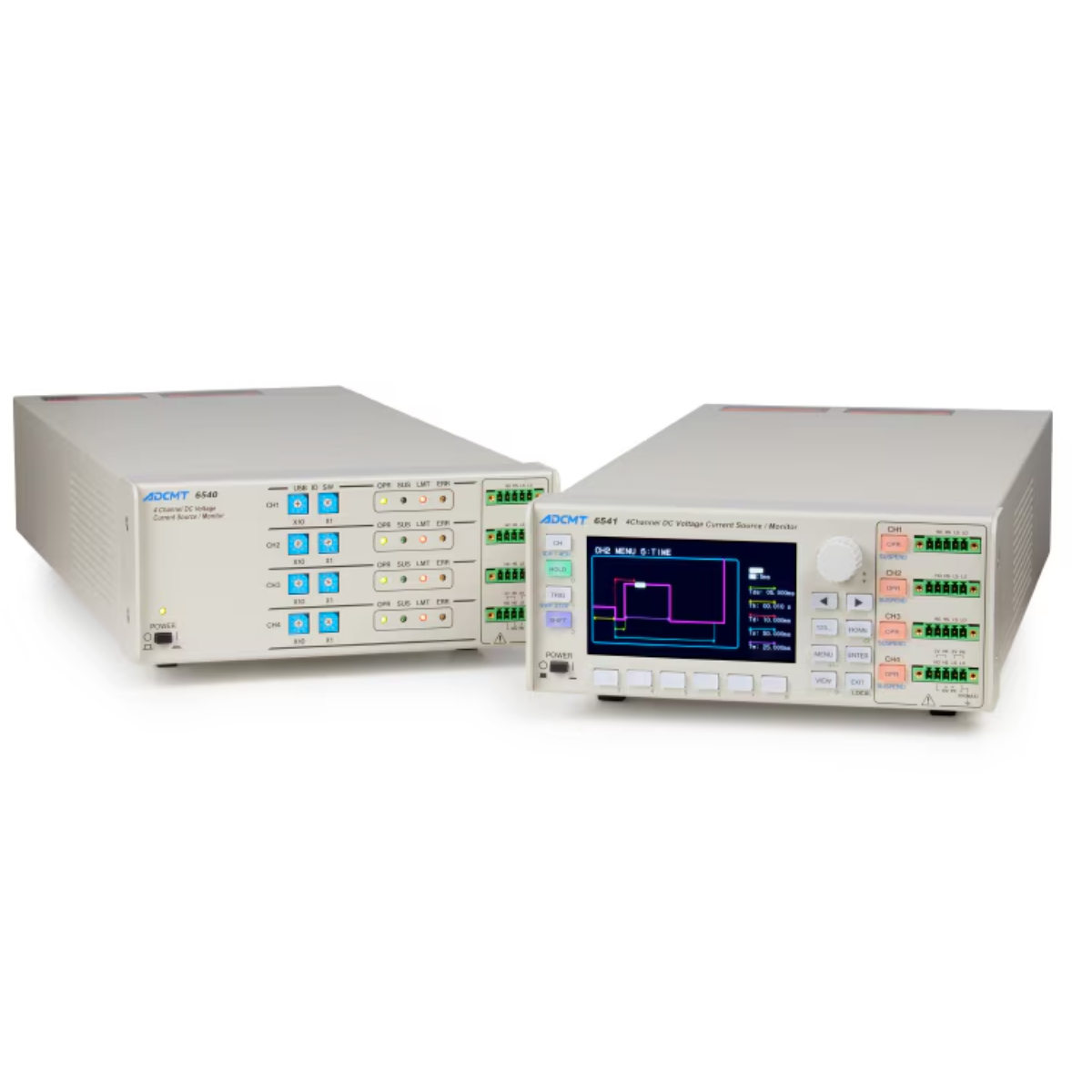
ADC 6540/6541 4-Ch DC Source Monitor
Request a Quote
The ADC 6540 and 6541 are compact 4-channel DC voltage/current source monitors designed for R&D and production testing.
Offering ±10 V and ±500 mA per channel (up to ±1 A for 4 channels), they deliver 0.02% accuracy and ultra-fine 10 μV/10 pA resolution.
With fast 50 μs pulse generation, synchronous operation, and selectable HI/LO limits, they support advanced evaluations from battery ICs to RF front-end modules. The 6541 includes a color LCD display for benchtop use, while the 6540 is optimized for system integration.
Features
Source and measurement functions

Voltage or current source, and voltage, current or resistance measurement can be selected by specifying the source and measurement functions. The LO terminals internally connected.
Output range
Voltage: 0 to ±10 V
Current: 0 to ±500 mA
The source range is common to 4 channels. The maximum current
for 4 channels is up to ±1 A
Operating temperature range
A: 0 °C to + 50 °C (0.5 W/ch or less at current sink)
B: 0 °C to + 40 °C (2.5 W/ch or less at current sink)
C: 0 °C to + 35 °C (5 W/ch or less at current sink)
Voltage and current source modes
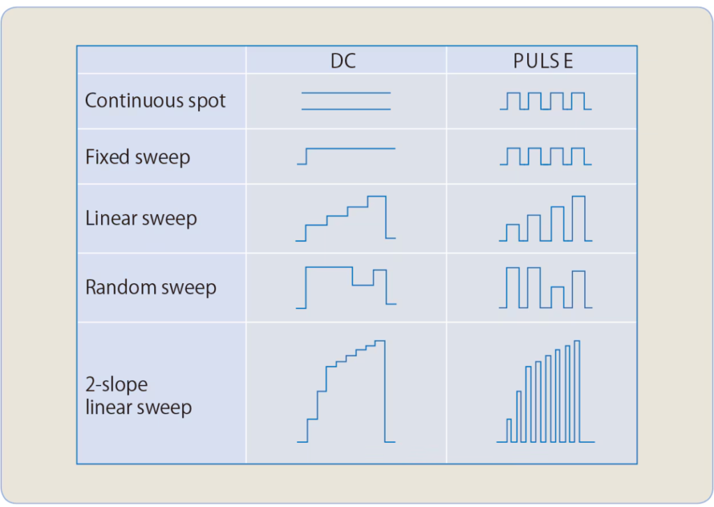
There are four voltage or current source modes; DC, pulse, DC sweep, pulse sweep. Then, the sweep modes are classified into four sweep types: fixed sweep, linear sweep, random sweep (arbitrary waveform generation by user programming), 2-slope linear sweep (linear sweep with step value switching).
The minimum pulse width is 50 μs.
The minimum cycle is 500 μs, or 100 μs without measurement.
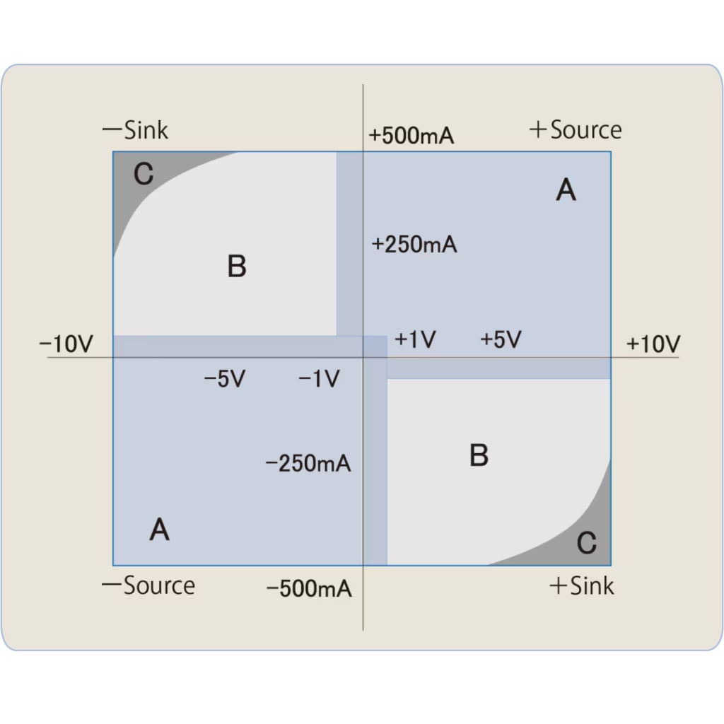
HI/LO limit separate setting
In voltage or current source, the HI/LO limit settings are very important. For current source, the limit (compliance) voltage must be higher than the applied voltage. When voltage higher than the limit voltage is applied from the outside, the instrument detects overload and sets standby. When a capacitor is discharged after being charged at a constant current with the positive and negative limits being set to the same value, overload occurs if the limit voltage is lowered. In addition, it is discharged down to negative voltage when applying reverse polarity current.
However, the 6540/6541 has a function that can set the HI and LO limits individually. Furthermore, for the voltage limit, both HI and LO limits can be set homo-polar. This prevents capacitors or batteries from being over-discharged. Also, it is suitable for evaluating devices such as LDs that are used at a constant current and do not tolerate reverse voltage application.
Suspend function
The 6540/6541 can select from three output OFF statuses; STBY (output relay OFF), HiZ (output relay ON and high resistance), and LoZ (output relay ON and low resistance). Consequently, unnecessary relay ON/OFF operations can be omitted. Using this function will prevent throughput reduction due to relay operating time, and extend relay lifetime dramatically, increasing product reliability.
In addition, the setting of a suspend voltage (voltage in HiZ and LoZ status) can prevent transient current from being generated when connecting voltage sourcing devices such as batteries.
| Output OFF status | Output relay | Output status | Current limit setting value |
| LoZ | ON | Vsus, low resistanc |
VS: Setting current limit (IL) IS: 30 digits in the setting current range (100 digits for the 3 µA range) |
| HiZ | ON | Vsus, high resistance | 100 nA |
| STBY | OFF | Open | - |
Vsus: Setting suspend voltage (default: 0 V)
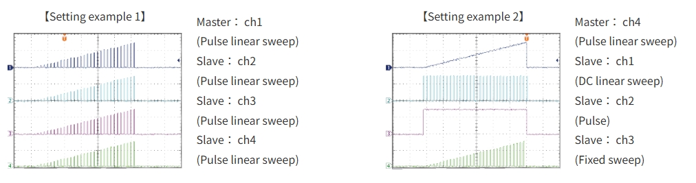
Synchronous source and measurement
The 6540/6541 can synchronize measurements in the DC source mode, and sources and measurements in the pulse source or sweep source mode. Not only the same waveforms but also different waveforms can be generated or measured. Arbitrary master channel and slave channels are selectable.
6540 standard control software
The 6540 has no control panel because of its system-use structure, but it has a control program so to be operated externally from a PC via USB. This software makes it possible the basic operations including source, measurement and limit control.
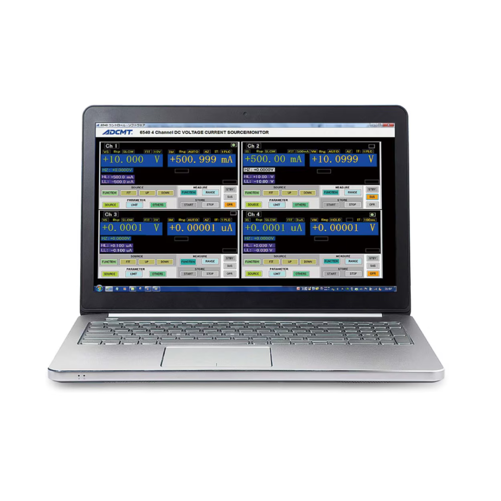
Display screen
The home screen is selectable from two types: 1-channel display and 4-channel display. Also, each channel can be set by using soft keys and rotary knob.
【[1-channel view】
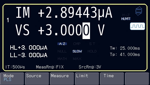
Displays various information such as source ranges, periods and integration time in addition to source voltage or current, measurement voltage, current or resistance, and limit voltage or current values.
【[4-channel view】
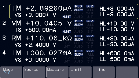
Displays source voltage or current, measurement voltage, current or resistance, and limit voltage or current values of all channels.
【Time setting view]】
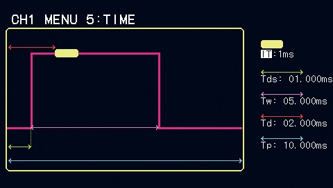
Measurement time setting is very important for pulse or sweep measurement.
Using the time setting screen allows easier and more sensuous operations than former models.
Using the time setting screen allows easier and more sensuous operations than former models.
Applications
Peak current and average current measurements for mobile phones
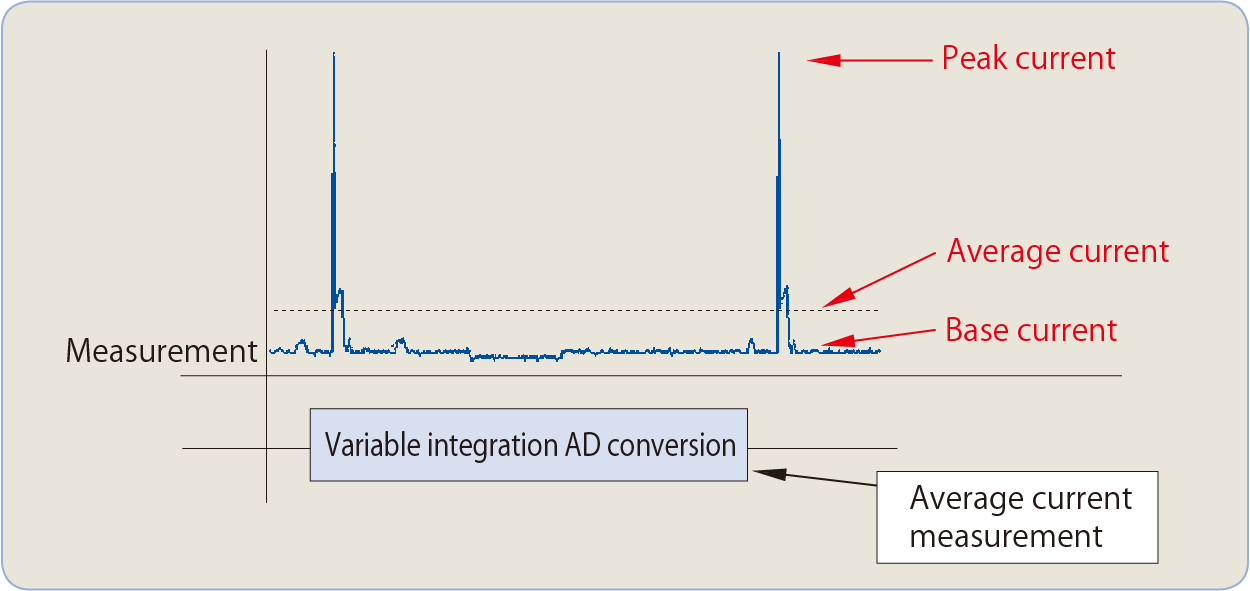
In the standby state of mobile phones, the base current usually flows and the peak current flows at a constant period. To measure the average current precisely, it is necessary to measure all current passing during the standby state. The 6540/6541 is capable of accurate average current measurement by measuring the peak current and using the variable integration function.
Average current measurement [variable integration function]
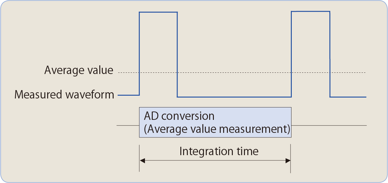
The 6540/6541 allows you to set the integration time arbitrarily from 100 μs to 740 ms. This makes it measure easily the average current consumption of mobiles phones and LCDs.
As the integration time of the AD converter itself can be set, and analog integration is adopted, there are no omissions in waveforms differently from digital integration, resulting in precise average measurement.
Peak current measurement [peak hold measurement function]
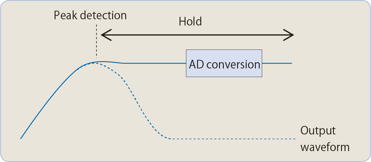
The 6540/6541 is capable of peak hold measurement at pulse generation. The peak hold measurement function detects and measures the maximum value in a pulse at a frequency of up to 20 kHz. The integration time is 1 ms and the maximum executable period is 600 ms.
Battery management IC evaluation
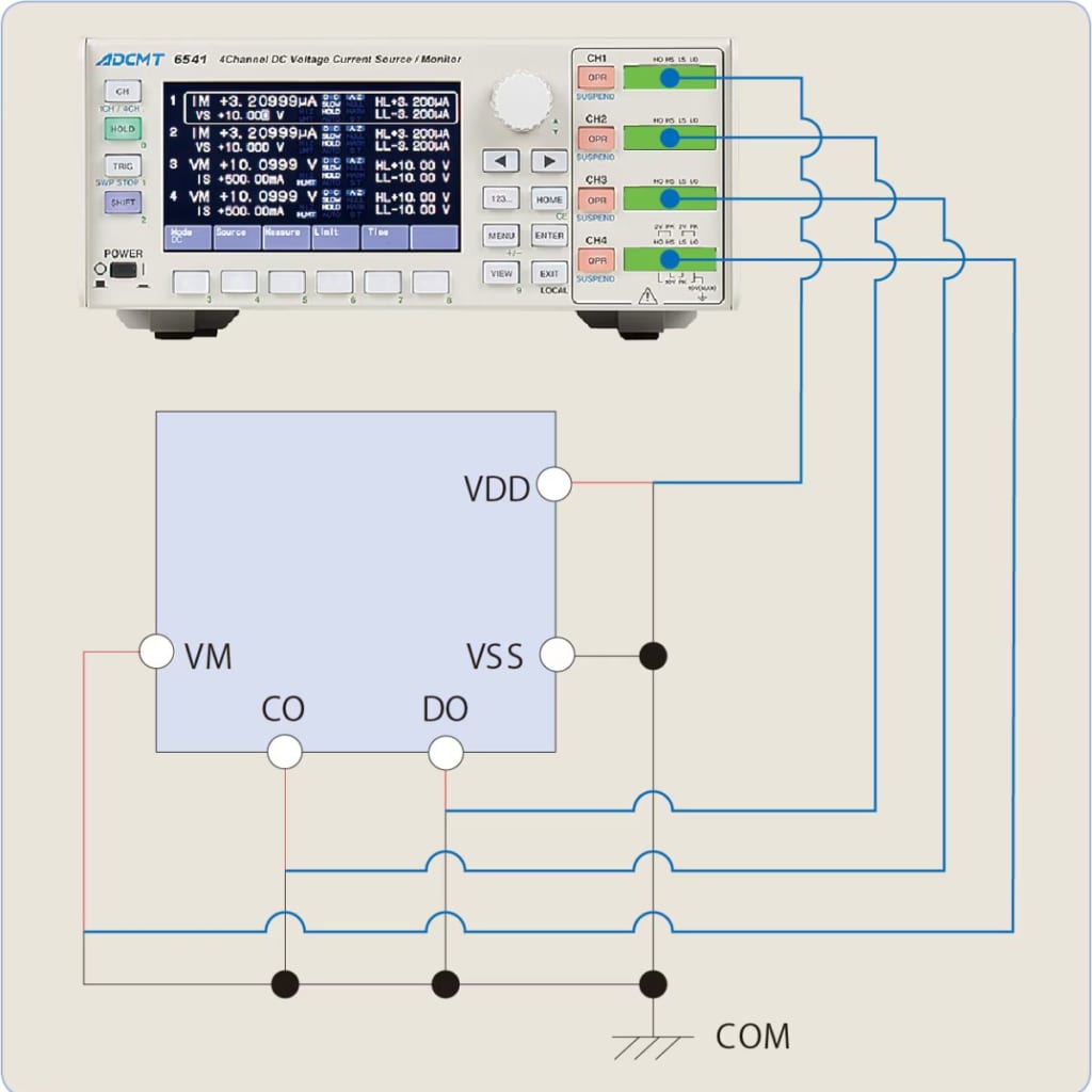
To evaluate various ICs such as battery management IC, the 6540/6541 generates constant voltage or current and also measures voltage and current.
It measures how DO or CO operates when varying VDD or VM, and measures current against applied voltage to each terminal.
- Voltage application: -10 V to +10 V
- Voltage measurement resolution: 100 μV (10 V range)
- Current measurement resolution: 10 pA (3 μA range)
Bias source for communication LDs and PDs
The 6540/6541 works as bias source for photo detectors (PDs) used in receivers for digital coherent communication.
- Voltage output noise
4 mVp-p (3 V range, DC to 20 MHz)
5 mVp-p (10 V range, DC to 20 MHz) - Current measurement resolution
100 nA (30 mA range), 1 µA (500 mA range)
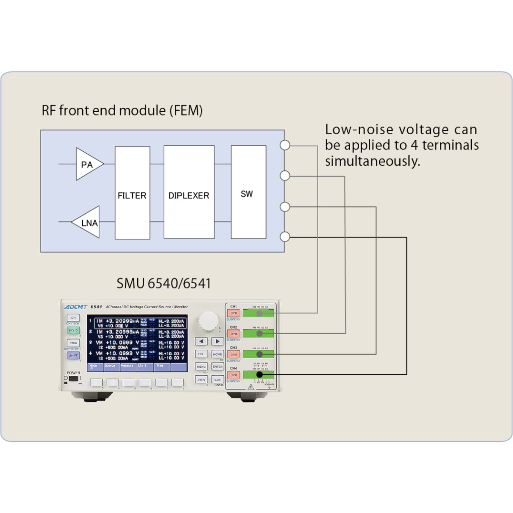
RF front end module evaluation
The 6540 and 6541 are 4-channel compact DC Voltage Current Source/
Monitors having a low-noise feature (10 V range: 5 mVp-p).
As synchronous source and measurement across the channels are
available, the 6540 and 6541 are capable of low-noise voltage source,
signal application and current measurement with the minimum resolution of 10 pA by a single unit, and are suitable for evaluation of RF front end modules that require controlling multiple terminals at the same time.
(Maximum power per channel: ±10 V / ±500 mA, ±1 A for 4 channels)
Specification
| 6540 | 6541 | ||
| Number of digits for generation | 4½ digit | ||
| Output method | Bipolar | ||
| Maximum output (top)
Minimum resolution (bottom) |
Voltage |
±10 V / 500 mA (1 A for 4 channels) |
|
| 100 μV | |||
| Current | ±500 mA / 10 V (1 A for 4 channels) | ||
| 100 pA | |||
| Number of digits for measurement | 5½ | ||
| Accuracy (typical range) | 0.02 % | ||
| Minimum measurement resolution | Voltage | 10 μV | |
| Current | 10 pA | ||
| Output noise (20 MHz or less) | 4 mVp-p | ||
| Minimum pulse width | 50 μs | ||
| Display | None (LED indicators only) | 4.3 inch color LCD display | |
| Interface | USB port per channel
4 USB ports in total |
Single USB port
GPIB port (option) LAN port (option) |
|
![]()
To view the pdf files, the Adobe Reader from Adobe Systems is required.