This website uses cookies so that we can provide you with the best user experience possible. Cookie information is stored in your browser and performs functions such as recognising you when you return to our website and helping our team to understand which sections of the website you find most interesting and useful.

ITEMLIST
Products Infomation

- Products by Category
- Automotive&EV
- Kyowa Wireless Digital Telemeter MRS-100 Series
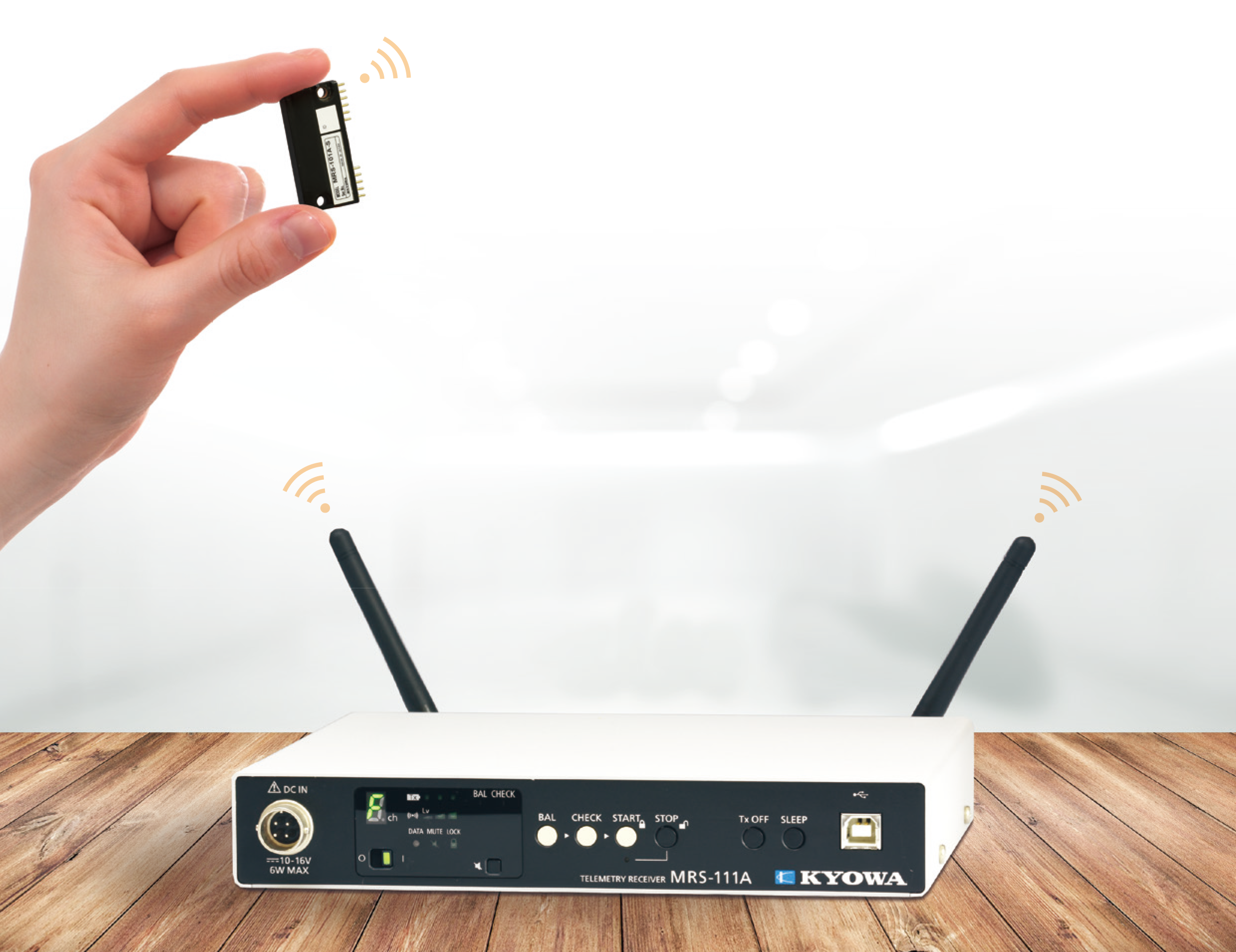
Making Measurement "Wireless" MRS-100 Series
The Digital Telemeter MRS-100 series is a telemeter for various measuring environments, based on the digital modulation system.
The MRS-100 series measures data of max. 50 m range (line of sight distance) wirelessly. Compact transmitter and easy installation in narrow space.
Digital Telemeter
Model:
MRS-100 Series
Maker:
Kyowa Electronic Instruments
Features
• Easy operation without PC after initial setting
• Quarter-bridge 2-wire system, 3-wire system, and full-bridge system support
• Up to 64 channels in a system
• Certified in radio law in Japan, the USA, China, India, Thailand, Taiwan, EU (Depends on models)
• Hours of continuous use: Max. 34 h (1ch-Strain Transmitter using LR03EJ, AAA cell × 2)
Application
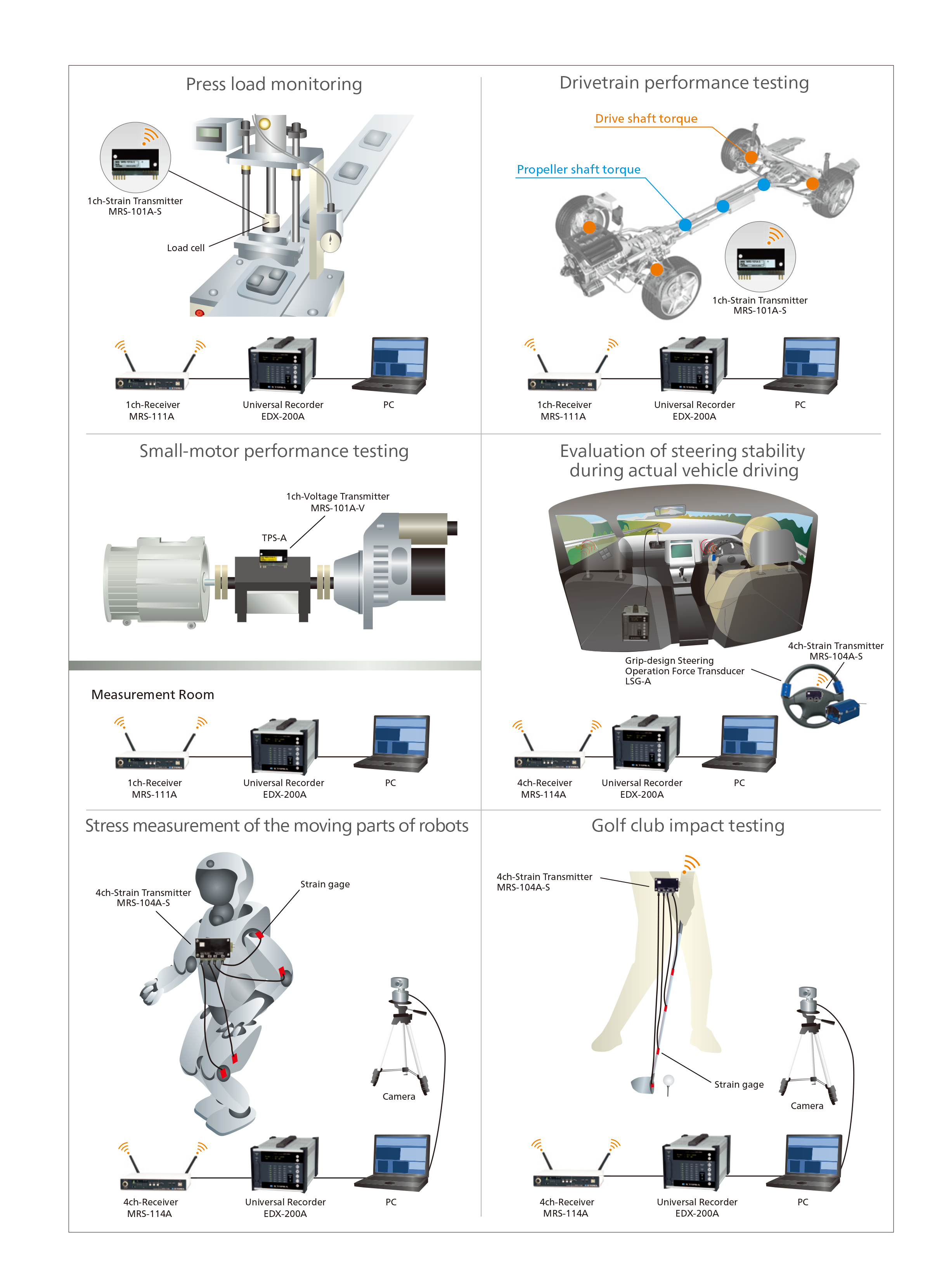
The MRS-100 Series is a lineup of small wireless units that enable to achieve stable communication with digital modulation, and this series can be used to easily make a strain-gage sensor or voltage-output sensor wireless. The MRS-100 Series can therefore be used to respond to rapid events in the automobile-related and other experiment and research fields, and the testing data can be sent almost in real-time. In addition, because the unit can be incorporated into a production line to make the load, pressure, and other sensors used for quality control wireless, it is useful for improving productivity.
Specifications
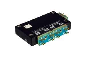
MRS-104A-S 4ch-Strain Transmitter
| Measuring Targets | Strain gages (Full bridge system*) Strain-gage transducers*Other bridge systems need bridge box or bridge adapter. |
|---|---|
| Channels | Max. 4 |
| Compatible Bridge Resistance | 120 to 1000 Ω |
| Gage Factor | 2.00 fixed |
| Bridge Excitation | 1 VDC |
| Measuring Range | 1000, 2500, 5000, 10000, 25000 ×10-6 strain |
| Measuring Accuracy | Within ±0.15% FS *The specifications apply to a stable temperature after warm up for about 30 minutes in an 25 ±5℃ environment. |
| Balance Adjustment Range | Within ±10000 ×10-6 strain |
| AD Resolution | 16 bits |
| Sampling Frequencies | 1 channel: 4.8 kHz 2 channels: 3.2 kHz 3 channels: 2.4 kHz 4 channels: 1.92 kHz |
| Temperature Stability | Zero point: Within ±0.05 ×10⁻⁶ strain per °C Sensitivity: Within ±0.01%/°C |
| Operating Temperature | -25 to 75°C
*If the ambient temperature exceeds 50°C, it cannot be used in a vibration, shock, centrifugal acceleration by fixing the bolts in the body mounting holes. |
| Operating Humidity | 20 to 85% (Non-condensing) |
| Vibration Resistance | 294.2 m/s2 (30 G), 10 to 500 Hz
*If the ambient temperature exceeds 50°C, it cannot be used in a vibration, shock, centrifugal acceleration by fixing the bolts in the body mounting holes. |
| Shock Resistance | 980.7 m/s2 (100 G), 11 ms or less, half sine wave
*If the ambient temperature exceeds 50°C, it cannot be used in a vibration, shock, centrifugal acceleration by fixing the bolts in the body mounting holes. |
| Centrifugal Acceleration Resistance |
980.7 m/s2 (100 G) *If the ambient temperature exceeds 50°C, it cannot be used in a vibration, shock, centrifugal acceleration by fixing the bolts in the body mounting ho les. |
| Power Supply | 2.2 to 4.4 VDC |
| Current Consumption | Within 62 mA (Test conditions: Power supply 3.0 V, bridge resistance 120 Ω) |
| Hours of Continuous Use | Approx. 12 h [Lithium (CR2 manufactured by Panasonic)] Approx. 10 h [Ni-MH eneloop® (BK-4MCC, AAA cell×2)] Approx. 13 h [Alkaline EVOLTA (LR03EJ, AAA cell×2)] *Test conditions: 23 ±5°C, bridge resistance 120 Ω |
| Dimensions | 55 W × 10 H × 32.5 D mm (Excluding protrusions, with adapter) |
| Weight | Approx. 32 g (With adapter) |
| Compliance | Directive 2014/53/EU (RED) Directive 2011/65/EU, (EU) 2015/863 (10 restricted substances) (RoHS) |
RF Specifications
| Transceiver Frequency Channel | 1 (Choose 1 channel from 16 channels using Setting software) |
|---|---|
| Antennas | Built-in |
| Radio Communication Frequency Band | 2.4 GHz band |
| Radio Certification | Digital modulation system |
| Dimensions | Japan, the USA, China, India, Thailand, Taiwan, EU |
| Communication Distance | 50 m (Max. line of sight distance) |
| Environment of Usage | Environment where the wireless LAN and the Bluetooth🄬, etc. are not intermingled on the 2.4 GHz. |
| Frequency Channel and Central Frequency | Frequency channel————–Central frequency (GHz) CH 0——————————–2.405 CH 1——————————–2.410 CH 2——————————–2.415 CH 3——————————–2.420 CH 4——————————–2.425 CH 5——————————–2.430 CH 6——————————–2.435 CH 7——————————–2.440 CH 8——————————–2.445 CH 9——————————–2.450 CH A——————————–2.455 CH B——————————–2.460 CH C——————————–2.465 CH D——————————–2.470 CH E——————————–2.475 CH F——————————–2.480Communication is not possible if there are multiple transmitters with the same radio Frequency Channel in the system. |
Combination Specifications of Transmitter with Receiver
| Compatible Receiver | MRS-114A firmware ver. 3.00 or later
*No MRS-104A-S be used in combination with a 1-channel receiver. |
|---|---|
| Analog Output Voltage | ±5 V/Full scale range |
| Combination Measuring Accuracy | Within ±0.2% FS |
| Frequency Response | Measuring channel: 1 Sampling frequencies: 4.8 kHz Frequency response: DC to 370 Hz (Deviation +0.5, -1dB), -3 ±1 dB (at 480 Hz)Measuring channels: 2 Sampling frequencies: 3.2 kHz Frequency response: DC to 320 Hz (Deviation +0.5, -1dB), -3 ±1 dB (at 466 Hz)Measuring channels: 3 Sampling frequencies: 2.4 kHz Frequency response: DC to 240 Hz (Deviation +0.5, -1dB), -3 ±1 dB (at 424 Hz)Measuring channels: 4 Sampling frequencies: 1.92 kHz Frequency response: DC to 192 Hz (Deviation +0.5, -1dB), -3 ±1 dB (at 376 Hz) |
| Delay Time | Measuring channel: 1 Sampling frequencies: 4.8 kHz Delay time: 11.1 ±0.3 ms (at DC to 480 Hz)Measuring channels: 2 Sampling frequencies: 3.2 kHz Delay time: 10.8 ±0.3 ms (at DC to 320 Hz)Measuring channels: 3 Sampling frequencies: 2.4 kHz Delay time: 9.8 ±0.3 ms (at DC to 240 Hz)Measuring channels: 4 Sampling frequencies: 1.92 kHz Delay time: 9.7 ±0.3 ms (at DC to 192 Hz)Only 1 transmitter can be used in combination with 1 receiver. No MRS-104A-S be used in combination with a 1-channel receiver. 2 or more measuring channels are for 4-channel transmitter with 4-channel receiver. |
| Standard Accessories | Full-bridge adapter ADP-401 × 2 JCIS10-70 miniature screw (M2 × 4) × 3 Power adapter ADP-40P The above are installed in the transmitter.Fastening bracket × 2 Battery holder (AAA cell × 2) for checking operation ID label |
| Optional Accessories | Quarter-bridge 2-wire adapter (120 Ω) ADP-402-120 (2 channels/pc) Quarter-bridge 3-wire adapter (120 Ω) ADP-403-120 (2 channels/pc) Full-bridge adapter ADP-401 Power adapter ADP-40P MRS 4ch junction kit MRS-J14A |
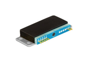
MRS-101B-S 1ch-Strain Transmitter
| Measuring Targets | Strain gages (Full bridge system*) Strain-gage transducers*Other bridge systems need bridge box or bridge adapter. |
|---|---|
| Channels | 1 |
| Compatible Bridge Resistance | 120 to 1000 Ω |
| Gage Factor | 2.00 fixed |
| Bridge Excitation | 1 VDC |
| Measuring Range | 1000, 2500, 5000, 10000, 25000 ×10-6 strain |
| Measuring Accuracy | Within ±0.15% FS *The above specifications apply to a stable temperature after warm up at 25 ±5℃ for 30 minutes. |
| Balance Adjustment Range | Within ±10000 ×10-6 strain |
| AD Resolution | 16 bits |
| Sampling Frequencies | 4.8 kHz |
| Temperature Stability | Zero point: Within ±0.05 ×10⁻⁶ strain per °C Sensitivity: Within ±0.01%/°C |
| Operating Temperature | -25 to 75°C |
| Operating Humidity | 20 to 85% (Non-condensing) |
| Vibration Resistance | 294.2 m/s2 (30 G), 10 to 500 Hz |
| Shock Resistance | 980.7 m/s2 (100 G), 11 ms or less, half sine wave |
| Centrifugal Acceleration Resistance |
29420 m/s2 (3000 G) *1, *2 *1 The figures are when installed with our specified screws and torque. |
| Power Supply | 2.2 to 4.4 VDC |
| Current Consumption | Within 32 mA (Test conditions: Power supply 3.0 V, bridge resistance 120 Ω) |
| Hours of Continuous Use | Approx. 28 h [Lithium (CR2 manufactured by Panasonic)] Approx. 24 h [Ni-MH eneloop® (BK-4MCC, AAA cell×2)] Approx. 34 h [Alkaline EVOLTA (LR03EJ, AAA cell×2)]*Test conditions: 23 ±5°C, bridge resistance 120 Ω |
| Dimensions | 47 W × 7 H × 20 D mm (Excluding protrusions, with adapter) |
| Weight | Approx. 17 g (With adapter) |
| Compliance | Directive 2014/53/EU (RED) Directive 2011/65/EU, (EU)2015/863 (10 restricted substances) (RoHS) |
RF Specifications
| Transceiver Frequency Channel | 1 (Choose 1 channel from 16 channels using Setting software) |
|---|---|
| Antennas | Built-in |
| Radio Communication Frequency Band | 2.4 GHz band |
| Radio Certification | Digital modulation system |
| Dimensions | Japan, the USA, China, India, Thailand, Taiwan, EU |
| Communication Distance | 50 m (Max. line of sight distance) |
| Environment of Usage | Environment where the wireless LAN and the Bluetooth🄬, etc. are not intermingled on the 2.4 GHz. |
| Frequency Channel and Central Frequency | Frequency channel————–Central frequency (GHz) CH 0——————————–2.405 CH 1——————————–2.410 CH 2——————————–2.415 CH 3——————————–2.420 CH 4——————————–2.425 CH 5——————————–2.430 CH 6——————————–2.435 CH 7——————————–2.440 CH 8——————————–2.445 CH 9——————————–2.450 CH A——————————–2.455 CH B——————————–2.460 CH C——————————–2.465 CH D——————————–2.470 CH E——————————–2.475 CH F——————————–2.480Communication is not possible if there are multiple transmitters with the same radio Frequency Channel in the system. |
Combination Specifications of Transmitter with Receiver
| Compatible Receiver | MRS-114A Firmware Ver. 3.01 or later MRS-111A (-E) Firmware Ver. 3.01 or later MRS-111B Firmware Ver. 3.01 or later |
|---|---|
| Analog Output Voltage | ±5 V/Full scale range |
| Combination Measuring Accuracy | Within ±0.2% FS |
| Frequency Response | DC to 370 Hz (Deviation +0.5, -1 dB) -3 ±1 dB (at 480 Hz) |
| Delay Time | 11.1 ±0.3 ms (at DC to 480 Hz)
Only 1 transmitter can be used in combination with 1 receiver. |
| Standard Accessories | Full-bridge adapter ADP-11S JCIS10-70 miniature screw (M2 × 4) The above are installed in the transmitter.Battery holder (AAA cell × 2) for checking operation ID label |
| Optional Accessories | MRS junction kit MRS-J11B Quarter-bridge 2-wire adapter (120 Ω) ADP-12S-120 Full-bridge adapter ADP-11S |
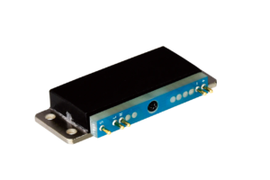
MRS-101B-T 1ch-Thermocouple Transmitter
| Measuring Targets | Thermocouples |
|---|---|
| Channels | 1 |
| Compatible Bridge Resistance | K, T, N, J (Resistance of thermocouple: 500 Ω or less) |
| Measuring Range | K1300: -200 to 1300ºC K500: -200 to 500ºC K100: -100 to 100ºC T400: -200 to 400ºC T100: -100 to 100ºC N1300: -200 to 1300ºC N500: -200 to 500ºC N100: -100 to 100ºC J1200: -200 to 1200ºC J500: -200 to 500ºC J100: -100 to 100ºC |
| Range Accuracy | Ambient temperature: 20 to 30ºC Measuring temperature: Below -50ºC Telemeter measuring accuracy (internal reference compensation mode): Within ±0.4%rdg ±2.0ºCAmbient temperature: 20 to 30ºC Measuring temperature: -50ºC or more Telemeter measuring accuracy (internal reference compensation mode): Within ±0.1%rdg ±1.5ºCAmbient temperature:0 to 50ºC Measuring temperature: Below -50ºC Telemeter measuring accuracy (internal reference compensation mode): Within ±0.4%rdg ±2.8ºCAmbient temperature: 0 to 50ºC Measuring temperature: -50ºC or more Telemeter measuring accuracy (internal reference compensation mode): Within ±0.1%rdg ±2.5ºCAmbient temperature:-25 to 75ºC Measuring temperature: Below -50ºC Telemeter measuring accuracy (internal reference compensation mode): Within ±0.4%rdg ±3.8ºC Ambient temperature: -25 to 75ºC
* The input terminal temperature is in equilibrium. |
| Check Function | Burnout check |
| AD Resolution | 16 bits |
| Sampling Frequencies | 50 Hz |
| Operating Temperature | -25 to 75°C |
| Operating Humidity | 20 to 85% (Non-condensing) |
| Vibration Resistance | 294.2 m/s2 (30 G), 10 to 500 Hz |
| Shock Resistance | 980.7 m/s2 (100 G), 11 ms or less, half sine wave |
| Centrifugal Acceleration Resistance |
29420 m/s2 (3000 G) * The figures are when installed with our specified screws and torque. |
| Power Supply | 2.2 to 4.4 VDC |
| Current Consumption | Within 24 mA (Test conditions: Power supply 3.0 V) |
| Hours of Continuous Use | Approx. 33 h [Lithium (CR2 manufactured by Panasonic)] Approx. 30 h [Ni-MH eneloop® (BK-4MCC, AAA cell×2)] Approx. 45 h [Alkaline EVOLTA (LR03EJ, AAA cell×2)]*Test conditions :23 ±5ºC |
| Dimensions | 47 W × 7 H × 20 D mm (Excluding protrusions, with adapter) |
| Weight | Approx. 17 g (With adapter) |
| Compliance | Directive 2014/53/EU (RED) Directive 2011/65/EU, (EU)2015/863 (10 restricted substances) (RoHS) |
RF Specifications
| Transceiver Frequency Channel | 1 (Choose 1 channel from 16 channels using Setting software) |
|---|---|
| Antennas | Built-in |
| Radio Communication Frequency Band | 2.4 GHz band |
| Radio Certification | Digital modulation system |
| Dimensions | Japan, the USA, China, India, Thailand, Taiwan, EU |
| Communication Distance | 50 m (Max. line of sight distance) |
| Environment of Usage | Environment where the wireless LAN and the Bluetooth🄬, etc. are not intermingled on the 2.4 GHz. |
| Frequency Channel and Central Frequency | Frequency channel————–Central frequency (GHz) CH 0——————————–2.405 CH 1——————————–2.410 CH 2——————————–2.415 CH 3——————————–2.420 CH 4——————————–2.425 CH 5——————————–2.430 CH 6——————————–2.435 CH 7——————————–2.440 CH 8——————————–2.445 CH 9——————————–2.450 CH A——————————–2.455 CH B——————————–2.460 CH C——————————–2.465 CH D——————————–2.470 CH E——————————–2.475 CH F——————————–2.480Communication is not possible if there are multiple transmitters with the same radio Frequency Channel in the system. |
Combination Specifications of Transmitter with Receiver
| Compatible Receiver | MRS-114A Firmware Ver. 3.01 or later MRS-111A (-E) Firmware Ver. 3.01 or later MRS-111B Firmware Ver. 3.01 or later |
|---|---|
| Analog Output Voltage | ±5 V/Full scale range |
| Combination Measuring Accuracy | Within ±0.2% FS |
| Frequency Response | DC to 370 Hz (Deviation +0.5, -1 dB) -3 ±1 dB (at 480 Hz) |
| Delay Time | 11.1 ±0.3 ms (at DC to 480 Hz)
Only 1 transmitter can be used in combination with 1 receiver. |
| Standard Accessories | Full-bridge adapter ADP-11S JCIS10-70 miniature screw (M2 × 4) The above are installed in the transmitter.Battery holder (AAA cell × 2) for checking operation ID label |
| Optional Accessories | MRS junction kit MRS-J11B Quarter-bridge 2-wire adapter (120 Ω) ADP-12S-120 Full-bridge adapter ADP-11S |
![]()
To view the pdf files, the Adobe Reader from Adobe Systems is required.