This website uses cookies so that we can provide you with the best user experience possible. Cookie information is stored in your browser and performs functions such as recognising you when you return to our website and helping our team to understand which sections of the website you find most interesting and useful.

ITEMLIST
Products Infomation

- Products by Category
- Automotive&EV
- KIKUSUI TOS5200 series
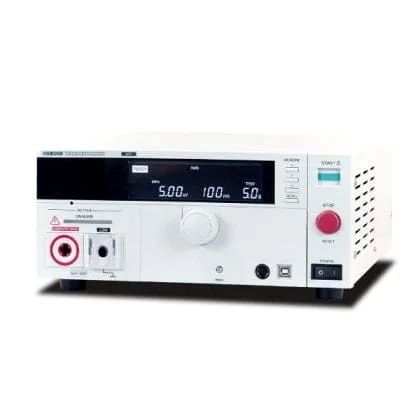
AC Hipot Tester with Stable PWM Output
U.S.-based sales, and delivery available.
The Kikusui TOS5200 is a high-stability AC Hipot Tester designed for reliable withstand voltage testing up to 5 kV / 100 mA. Using a PWM switching amplifier, it maintains stable output regardless of input voltage fluctuations.
With high measurement accuracy, fast test times down to 0.1 s, and comprehensive safety protections, it is ideal for IEC/UL-compliant production and inspection environments.
Overview
-
Highly stable output thanks to PWM amplifier
-
AC withstand voltage test: 5 kV / 100 mA (500 VA)
-
High accuracy measurement: ±1.5% of reading
(at 500 V or more for voltmeter and 1 mA or more for ammeter) -
Rise / fall time control
-
Key lock & actuator cover
-
Equipped with RS232C and USB interfaces
Overview
An ideal AC Hipot Tester with low cost of ownership realized, built on more than 50 years of experience in market
The TOS5200 AC withstand voltage tester is designed to perform withstand voltage tests, one of the four essential tests required to ensure the safety of electrical products. The output is 5 kV / 100 mA (AC), enabling withstand voltage testing of electronic equipment and components in accordance with the requirements of IEC, EN, UL, VDE, JIS, and other national safety standards, as well as the Electrical Appliance and Material Safety Law.
In addition, the newly developed switching amplifier improves test voltage stability, maintaining a constant output voltage even when AC line voltage or frequency fluctuates. This enables stable testing in regions with unstable power supply environments. A full range of functional features is provided to meet various testing needs. This is a standard, low-cost AC withstand voltage tester that is thoroughly designed for ease of operation, reliability, and safety.

Specifications
Withstand voltage tester section
| AC Output section | Output range | 0.05 kV to 5.00 kV | |
| Accuracy | ± (2 % of set + 20 V) when no load is connected | ||
| Operating range | 0.00 kV to 5.50 kV | ||
| Resolution | 10 V STEP | ||
| Max. rated output *1 | 500 VA (5 kV/100 mA) | ||
| Max. rated voltage | 5 kV | ||
| Max. rated current | 100 mA (when the output voltage is 0.5 kV or greater) | ||
| Transformer rating | 500 VA | ||
| Output voltage waveform *2 | Sine | ||
| Distortion | If the output voltage is 0.5 kV or more: 3 % or less (when no load or a pure resistive load is connected) | ||
| Crest factor | √ 2 ± 3 % less than (when the output voltage is 800 V or greater, no load) | ||
| Frequency | 50 Hz or 60 Hz | ||
| Accuracy | ± 0.5 % (excluding during voltage rise time) | ||
| Voltage regulation | 10 % or less (when changing from maximum rated load to no load) | ||
| Input voltage variation | ±0.3 % (5 kV when no load is connected; power supply voltage: 90 V to 250 V) | ||
| Short-circuit current | 200 mA or more (when the output voltage is 1.0 kV or greater) | ||
| Output method | PWM switching | ||
| Start voltage | The voltage at the start of withstanding voltage tests can be set to 50 % of the test voltage. | ||
| Limit voltage | The test voltage upper limit can be set . AC: 0.00 kV to 5.50 kV | ||
| Output voltage monitor feature | If output voltage exceeds the specified value + 350 V or is lower than the specified value – 350 V, output is turned off, and protective features are activated. | ||
| Voltmeter | Digital | Measurement range | 0.000 kV to 6.500 kV AC |
| Display | □ . □□□ kV | ||
| Accuracy | V < 500 V:± (1.5 % of reading + 20 V)、V ≧ 500 V: ±1.5 % of reading | ||
| Response*3 | True rms, Average value response/rms display switchable | ||
| Hold feature | After a test is finished, the measured voltage is retained until the PASS or FAIL judgment is cleared. | ||
| Ammeter | Digital | Measurement range | AC:0.00 mA to 110 mA |
| Display | i = measured current i < 1 mA:□ . □□□ mA 1 mA ≦ i < 10 mA:□ . □□□ mA 10mA ≦ i < 100 mA:□□ . □□ mA 100 mA ≦ i:□□□ . □ mA |
||
| Accuracy*4 | 1.00 mA ≤ i: ± (1.5 % of reading), i < 1.00 mA: ± (1.5 % of reading + 30 μA) | ||
| Response*3 | True rms, Average value response/rms display switchable | ||
| Hold feature | After a test is finished, the measured current value is retained until the PASS judgment is cleared. | ||
| Judgment feature | Judgment method and judgment operation |
|
|||||||||||||||||||||
| Upper limit setting | AC: 0.01 mA to 110 mA | ||||||||||||||||||||||
| Lower limit setting | AC: 0.01 mA to 110 mA / OFF | ||||||||||||||||||||||
| Judgment accuracy *4 | 1.00 mA ≤ i: ± (1.5 % of set), i < 1.00 mA: ± (1.5 % of set + 30 μA) | ||||||||||||||||||||||
| Current detection method | Calculates the current’s true rms value and compares this value with the reference value | ||||||||||||||||||||||
| Calibration | Calibrated with the rms of a sine wave using a pure resistive load | ||||||||||||||||||||||
| Time | Voltage rise time | 0.1 s to 10.0 s | |||||||||||||||||||||
| Resolution | 0.1 s | ||||||||||||||||||||||
| Voltage fall time | 0.1 s / OFF (only enabled when a PASS judgment occurs) | ||||||||||||||||||||||
| Test Time | 0.1 s to 999 s, can be turned off (TIMER OFF) | ||||||||||||||||||||||
| Resolution | 0.1 s to 99.9 s: 0.1 s0 / 100 s to 999 s: 1 s | ||||||||||||||||||||||
| Accuracy | ±(100 ppm + 20 ms) excluding Fall Time | ||||||||||||||||||||||
*1 Regarding the output time limits:
Taking size, weight, and cost into consideration, the heat dissipation capability of the voltage generator that is used for withstanding voltage tests has been designed to be one half that of the rated output. Use the TOS5300 Series within the following limits. If you use the product in a manner that exceeds these limits, the output section may overheat, and the internal protection circuits may be activated. If this happens, stop testing, and wait until the TOS5300 Series returns to its normal temperature.
| Ambient temperature | Upper limit setting | Pause time | Output time | |
| t ≤ 40 °C | AC | 50 mA < i ≤ 110 mA | Greater than or equal to the output time | 30 min. max. |
| i ≤ 50 mA | Not necessary | Continuous output possible | ||
(Output time = voltage rise time + test time + voltage fall time)
*2: Regarding the test voltage waveform: Waveform distortions may occur if an DUT whose capacitance is dependent on voltage (for example, an DUT that consists of ceramic capacitors) is connected as the load. However, if the test voltage is 1.5 kV, the effect of a capacitance of 1000 pF or less can be ignored.Because the product’s high-voltage power supply uses the PWM switching method, if the test voltage is 500 V or less, the switching and spike noise proportions are large. The lower the test voltage, the greater the waveform is distorted. *3: For both True rms and Mean-value response, 50 ms or above response time is required to satisfy the measurement accuracy. *4: Regarding ammeter and judgment accuracy: During AC withstanding voltage tests, current also flows in the stray capacitance of items such as the measurement leads and jigs. This current that flows in the stray capacitances is added to the current that flows in the DUT, and the sum of these currents is measured.Especially if you want to perform judgments with high sensitivity and accuracy, it is necessary to consider methods to limit the current that flows in these stray capacitances, such as by adding upper and lower limits.
| Output voltage | 1 kV | 2 kV | 5 kV |
| When using 350 mm long test leads that are suspended in air (TYP) | 2 μA | 4 μA | 10 μA |
| When using the accessory, high test lead TL31-TOS (TYP) | 16 μA | 32 μA | 80 μA |
In case of 70 % humidity or higher, it is considerable to add 50 μA on the Limit value.
Other features/interfaces
| Test mode | Double action feature | Tests can only be started by pressing and releasing STOP and then pressing START within 0.5 seconds of releasing the STOP switch. |
| Length of time to maintain a PASS judgment result | You can set the length of time to maintain a PASS judgment: 50 ms, 100 ms, 200 ms, 1 s, 2 s,5 s, or HOLD. | |
| Momentary feature | Tests are only executed while the START switch is held down. | |
| Fail mode feature | This feature enables you to prevent remotely transmitted stop signals from clearing FAIL judgments and PROTECTION modes. | |
| Timer feature | This feature finishes tests when the specified time elapses. | |
| Output voltage monitor feature | If output voltage exceeds “setting + 350 V” or is lower than “setting – 350 V,” the TOS5200 switches to PROTECTION mode, output is turned off, and testing finishes. | |
| Memory | Up to three sets of test conditions can be saved to memory. | |
| Key lock | Locks panel key operations (settings and changes). | |
| Protection functions | Under any of the following conditions, the TOS5200 switches to the PROTECTION state, immediately turns output off, and stops testing. A message is displayed on the screen. | |
| Interlock Protection | An interlock signal has been detected. | |
| Power Supply Protection | An error was detected in the power supply. | |
| Volt Error Protection | While monitoring the output voltage, a voltage outside of the rated limits was detected. AC or DC withstanding voltage tests: ±350 V | |
| Over Load Protection | During a withstanding voltage test, a value that is greater than or equal to the output limit power was specified. AC withstanding voltage test: 550 VA. | |
| Over Heat Protection | The internal temperature of the TOS5200 became too high. | |
| Over Rating Protection | During a withstanding voltage test, the output current was generated for a length of time that exceeds the regulated time. | |
| Remote Protection | A connection to or disconnection from the front- panel REMOTE connector was detected. | |
| SIGNAL I/O Protection | The rear-panel SIGNAL I/O connector’s ENABLE signal has changed. | |
| USB Protection | The USB connector has been disconnected while the TOS5200 was being controlled through the USB interface. | |
| Interface | USB | USB Specification 2.0 |
| RS232C*1 | D-SUB 9-pin connector on the rear panel (compliant with EIA-232-D) All functions other than the POWER switch and KEY-LOCK | |
| REMOTE | Front-panel 9-pin MINI DIN connector. By connecting an optional device to this connector, you can control the starting and stopping of tests remotely. | |
| SIGNAL I/O | Rear-panel D-sub 25-pin connector |
*1 “Talk mode” can be set, when RS232C is used as comunication interface.
| Talk mode | Description | ||
| 0 | It responds only for commands from PC. (Default setting) | ||
| 1 | It responds automatically for start and end test, and returns the status, setting value, measured value. | ||
| Response at start | <START> | ||
| Response at end of test | Status | <PASS>,<U_FAIL>,<L_FAIL>,<PROT>,<ABOUT> | |
| Setting value, Measured value | Test No., Programme No., Test mode, Measured voltage, Measured current, Test time | ||
SIGNAL I/O connector pinout
| PIN No | Signal name | I/O | Rear-panel D-sub 25-pin connector | |||||||||||||||
| 1 | INTERLOCK+ | I | If you open the positive and negative terminals, the output is turned off, and the TOS5300 Series is switched to Protection mode.
Open: The resistance between the two terminals is 1.2 kΩ or greater. Short: The resistance between the two terminals is 1 kΩ or less. |
|||||||||||||||
| 2 | PM0 | I |
Panel memory selection signal. The selection signal is latched on the rising edge of the input strobe signal to recall panel memory. * The selection of memory is prioritized over TEST SEL and AUTO SEL. |
|||||||||||||||
| 3 | PM1 | I | ||||||||||||||||
| 4 | NC | − | − | |||||||||||||||
| 5 | NC | − | − | |||||||||||||||
| 6 | NC | − | − | |||||||||||||||
| 7 | NC | − | − | |||||||||||||||
| 8 | NC | − | − | |||||||||||||||
| 9 | STB | I | Panel memory strobe signal input terminal. | |||||||||||||||
| 10 | TEST SEL | I | NA | |||||||||||||||
| 11 | AUTO SEL | I | NA | |||||||||||||||
| 12 | COM | − | Circuit’s common terminal | |||||||||||||||
| 13 | INTERLOCK- | I | If you open the positive and negative terminals, the output is turned off, and the TOS5300 Series is switched to Protection mode.
Open: The resistance between the two terminals is 1.2 kΩ or greater. Short: The resistance between the two terminals is 1 kΩ or less. |
|||||||||||||||
| 14 | HV.ON | O | ON during test and while voltage remains between output terminals | |||||||||||||||
| 15 | TEST | O | ON during test (except when voltage is rising or falling) | |||||||||||||||
| 16 | PASS | O | On for at least 0.2 seconds (the PASS HOLD time) when a PASS judgment occurs. On continuously when the PASS HOLD time is set to HOLD. | |||||||||||||||
| 17 | U-FAIL | O | Continuously ON when value over acceptable maximum is detected, and UPPER FAIL is determined | |||||||||||||||
| 18 | L-FAIL | O | Continuously ON when value under acceptable minimum is detected, and LOWER FAIL is determined | |||||||||||||||
| 19 | READY | O | ON during standby (READY status) | |||||||||||||||
| 20 | PROTECTION | O | ON while protection function is activated (PROTECTION ON) | |||||||||||||||
| 21 | START | I | Start signal input terminal | |||||||||||||||
| 22 | STOP | I | Stop signal input terminal | |||||||||||||||
| 23 | ENABLE | I | Start signal’s ENABLE signal input terminal: Shifts to the Protection status when the ENABLE signal changes | |||||||||||||||
| 24 | +24V | − | +24V internal power supply output terminal: Maximum output current 100 mA | |||||||||||||||
| 25 | COM | − | Circuit’s common terminal |
General specifications
| Display | LCD: LED backlight | ||
| Environment | Installation location | Indoors, at a height of up to 2000 m | |
| Spec guaranteed range temperature/ humidity | 5 °C to 35 °C (41 °F to 95 °F)/20 %rh to 80 %rh (no condensation) | ||
| Operating range temperature/ humidity | 0 °C to 40 °C (32 °F to 104 °F)/20 %rh to 80 %rh (no condensation) | ||
| Storage range temperature/ humidity | -20 °C to 70 °C (-4 °F to 158 °F)/90 %rh or less (no condensation) | ||
| Power supply | Nominal voltage range (allowable voltage range) | 100 VAC to 240 VAC (90 VAC to 250 VAC) | |
| Power consumption | When no load is connected (READY) | 100 VA or less | |
| When rated load isconnected | 800 VA max. | ||
| Allowable frequency range | 47 Hz to 63 Hz | ||
| Insulation resistance (between AC LINE and the chassis) | 30 MΩ or more (500 VDC) | ||
| Withstanding voltage (between AC LINE and the chassis) | 1500 VAC, one minute | ||
| Earth continuity | 25 AAC, 0.1 Ω or less | ||
| Electromagnetic compatibility (EMC) *1 | Complies with the requirements of the following directive and standard. EMC Directive 2014/30/EU EN 61326-1(ClassA *2), EN 55011(ClassA *2, Group1 *3) EN 61000-3-2, EN 61000-3-3 Applicable under the following conditions The maximum length of all cabling and wiring connected to the TOS5200 must be less than 2.5 m. The shielded cable is being used when using the SIGNAL I/O. The high test lead TL31-TOS |
||
| Safety *1 | Complies with the requirements of the following directive and standard. Low Voltage Directive 2014/35/EU, EN 61010-1 (Class I *4 Pollution degree 2) |
||
| Dimensions (mm(inches))(maximum) | 320 (12.6″) (330(12.99″)) W × 132(5.2″) (150(5.91″)) H × 350(13.78″) (420(16.54″)) D | ||
| Weight | Approx. 14 kg (30.9 lbs) | ||
| Accessories | Power cord : 1pc. / High test lead (TL31-TOS) : 1set (1 red wire and 1 black wire, each with alligator clips); 1.5 m / D-sub 25-pin plug : 1set ; assembly type / High-voltage warning sticker : 1pc. / Setup Guide / Quick Reference(1 each for English and Japanese) / Safety informaion / CD-R *5 | ||
*1: Only on models that have the CE marking on the panel. Although signals are insulated with output terminals, each signal is common. Logic setting is also possible. *2: This is a Class A equipment. This product is intended for use in an industrial environment. This product may cause interference if used in residential areas. Such use must be avoided unless the user takes special measures to reduce electromagnetic emissions to prevent interference to the reception of radio and television broadcasts. *3: This is a Group 1 equipment. This product does not generate and/or use intentionally radio- frequency energy, in the form of electromagnetic radiation, inductive and/or capacitive coupling, for the treatment of material or inspection/analysis purpose. *4: This is a Class I equipment. Be sure to ground this product’s protective conductor terminal. The safety of this product is only guaranteed when the product is properly grounded. *5: Contains the User’s Manual, the Cimmunication Interface Manual, VISA library (KI-VISA), IVI-COM driver, and Safety evaluation test.
![]()
To view the pdf files, the Adobe Reader from Adobe Systems is required.