This website uses cookies so that we can provide you with the best user experience possible. Cookie information is stored in your browser and performs functions such as recognising you when you return to our website and helping our team to understand which sections of the website you find most interesting and useful.

ITEMLIST
Products Infomation

- Products by Category
- Electronic Measuring Instruments
- Electrical Safety Testers / Measuing Instruments
- KG MedTEST system

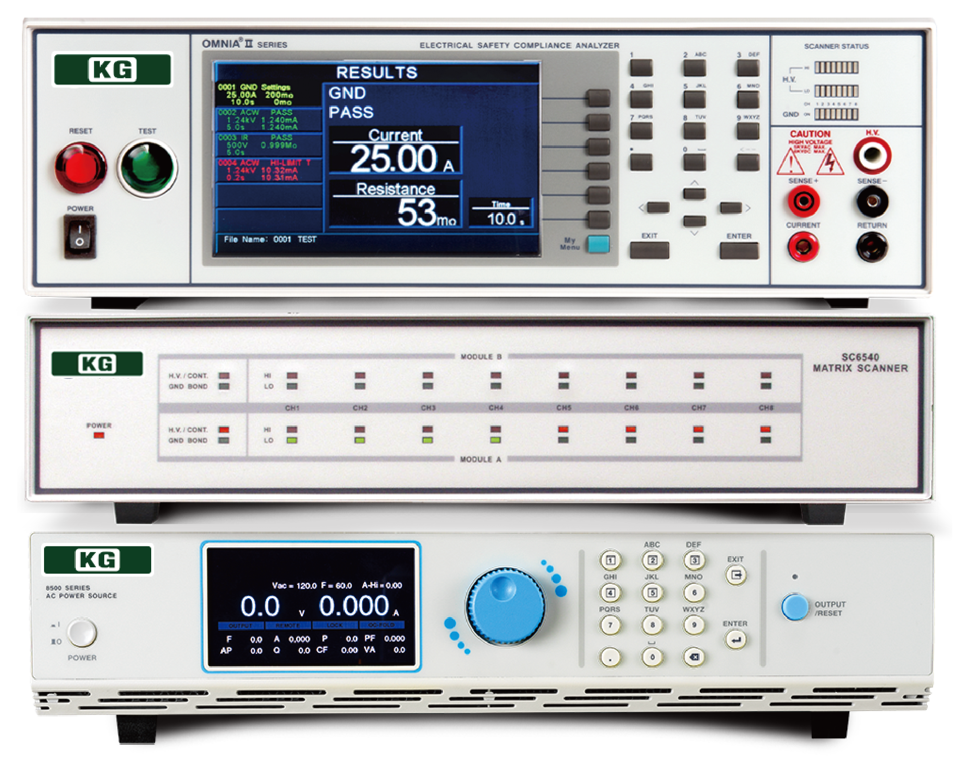
Medical device safety standard compliance system

MedTEST is a system designed to provide a complete testing solution for medical device manufacturers who must comply with international certification standards (such as IEC/UL60601-1 3rd Edition).
MedTEST can be customized to meet specific test requirements, such as withstand voltage, earth bond, insulation resistance, and leakage current testing (including live testing) for all Type B, Type BF, and Type CF applied parts. Additionally, the SC6540 matrix scanner allows for multi-switching between various measurement points, allowing tests to be performed sequentially without changing the measurement points on the test leads, reducing overall test time.
Medical device safety standard compliance system
Maker:
Features
All medical safety tests are packaged. The most advanced standard safety system
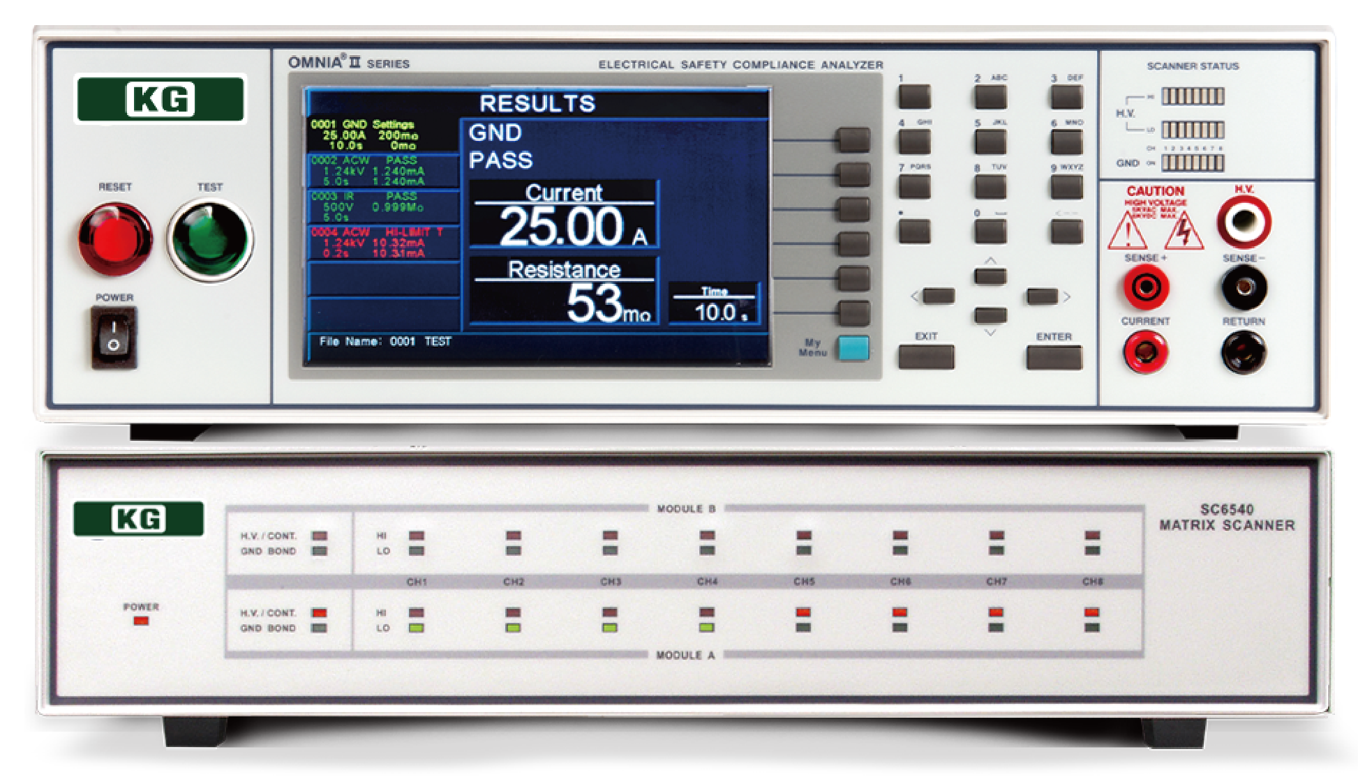
Safety Compliance Analyzer (8207)
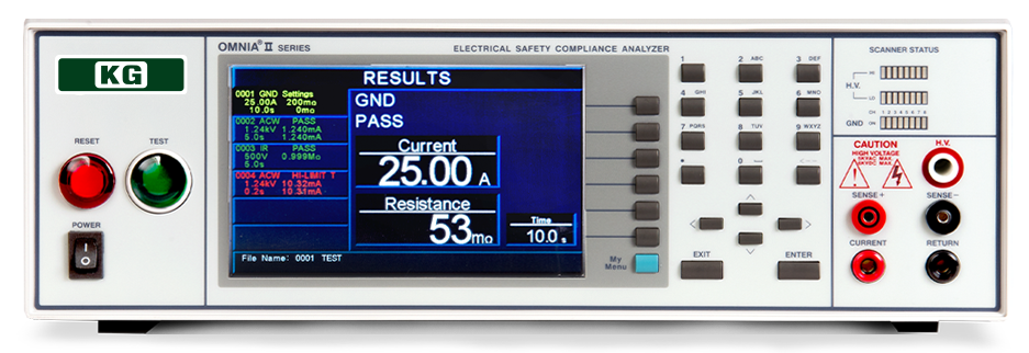
Extensive basic specifications
In addition to the conventional withstand voltage test (AC, DC) and insulation resistance test, earth continuity test and touch current test are also included as standard.
| AC withstand voltage | DC withstand voltage | Insulation resistance | Earth Continuity | Touch Current | RUN test | AC power supply |
| 5kV 50mA |
6kV 20mA |
1000V 50GΩ |
40A 600mΩ AC8V |
16A/277Vac DC, 15Hz-1MHz 10mArms/10mAp-p MD7 circuit built-in |
Standard equipment | Built-in as standard equipment (500VA) |
Withstand voltage test possible while power is on
It is possible to perform voltage withstand tests while the DUT (device under test) is powered on, and complies with Chinese standard GB/T 12350-2009 for more demanding quality testing.
Dual check function that reduces test time
Earth continuity tests (GB) and withstand voltage tests (ACW, DCW), which were previously performed separately, can now be performed simultaneously. This reduces the total test time and allows for more efficient testing.
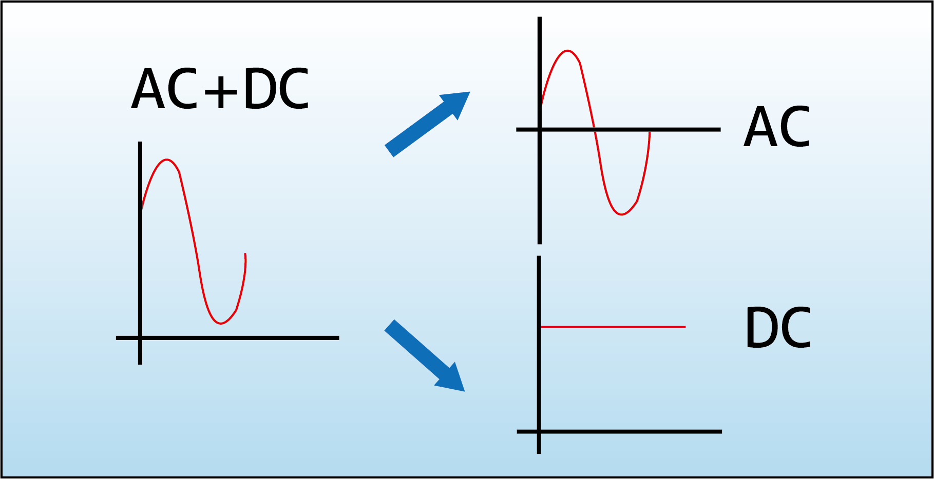
Current measurement function compliant with IEC60601
Previously, touch current (leakage current) measurements were made by combining AC and DC, but now, in compliance with the measurement standards of IEC60601 (safety standards for medical electrical equipment), it is possible to measure AC and DC separately from the AC+DC measurement value.
RUN test function: Power measurement function
Is the device broken after a withstand voltage test? Measures voltage, current, and power. Equipped with a function that judges the device as NG if the threshold value for normal products is exceeded.
Supports supply test voltage up to 277V
General testers are limited to 240V, and cannot perform 110% voltage application tests for export medical devices. This tester supports a maximum of 277V, allowing testing at 110% of 240V, or 264V. The input current rating is 16A.
Built-in 500VA isolated AC power supply
Built-in VVVF isolated AC power supply of 0 to 277V/0 to 4.2A/500VA
Freely designable external MD circuit available
A removable external MD is provided, allowing you to freely create simulated circuits. You can quickly support simulated circuits of new standards.
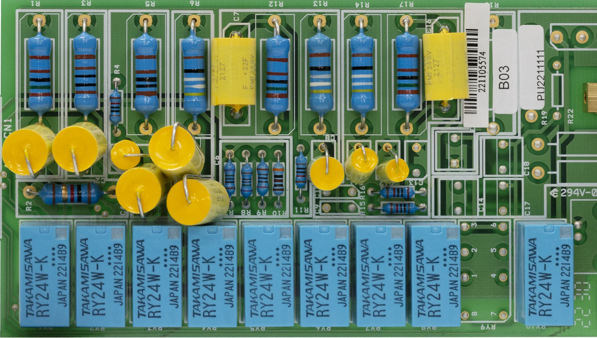
MD circuit unit
Visualization of MD circuits (human body simulated resistance)
The circuit unit, which was previously a black box, can now be detached. The circuit can be visually checked (error range and circuit pattern). When receiving approval for type testing from a certification body, error ranges and other information can be made visible and open.
Equipped with uninterruptible polarity switching function
Switching the input polarity is the same as a power outage if the voltage is dropped. Air conditioners and refrigerators take time to stabilize after a power outage, making it impossible to test immediately. Switching the polarity of the measurement side, rather than switching the polarity, allows for uninterruptible electrode switching.
Matrix scanner (SC6540)
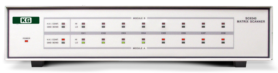
Uses a matrix scanner system for easy switching
The matrix scanner method allows the scanner to be set to one of three states: H: High voltage side, L: Return side (GND), and X: Open, as a switching method for the voltage and insulation resistance scanner.With a wide range of rated voltages of AC5kV/DC6kV, it can be used for multiple purposes, such as leakage current (touch current) and 110% AC voltage application required for medical device testing, in addition to withstand voltage and insulation resistance.
| ch | situation |
| ch1 | H |
| ch2 | L |
| ch3 | × |
| ch4 | H |
| ch5 | L |
| ch6 | × |
| ch7 | × |
| ch8 | × |
Multi-function, slim AC power supply (8500 STD series)
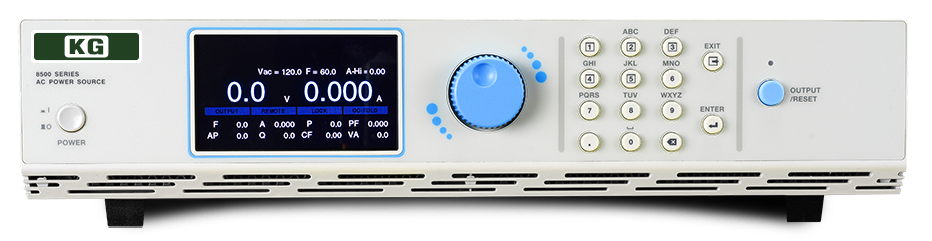
Capacity can be expanded using AC power supply (8500 STD series)
The Safety Standards Analyzer 8207 can supply up to 500VA with its built-in AC power supply, but by expanding the AC power supply with the Touch Current Tester 620L, it can support medical equipment up to single-phase 40Arms.
Compliant with Annex K of IEC62354. Pre-operation inspection jigs for safety testers and leakage current testers are provided.
– TVB-2
The TVB-2 is a fixture box for verifying that the safety tester is functioning properly. It is used before starting withstand voltage, insulation resistance, and earth bond tests to check that the safety tester is operating correctly.
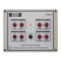
TVB-2
– LVB-2
LVB-2 is a jig box for checking that the leakage current tester is functioning properly. It is used before starting a leakage current test to check that the leakage current tester is operating correctly.
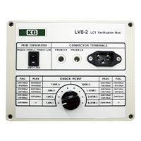
LVB-2
Composition
8207+SC6540 System Standard Type
- Standard all-in-one test system
(AC/DC withstand voltage, earth bond, insulation resistance, leakage current) - Built-in 500VA isolated AC power supply
- Multipoint switching test using SC6540 (8ch or 16ch)
| AC withstand voltage | DC withstand voltage | Insulation resistance | Earth Continuity | Touch Current | RUN test | AC power supply | Multipoint |
| 5kV 50mA |
6kV 20mA |
1000V 50GΩ |
40A 600mΩ AC8V |
16A/277Vac DC, 15Hz-1MHz 10mArms/10mAp-p MD7 circuit built-in |
Standard equipment | Built-in as standard equipment (500VA) |
8ch or 16ch |
8206+SC6540+8500 STD system extended type
- All-in-one test system with expanded AC power supply
(AC/DC withstand voltage, earth continuity, insulation resistance, leakage current) - Built-in 500VA isolated AC power supply
- Multipoint switching test using SC6540 (8ch or 16ch)
| AC withstand voltage | DC withstand voltage | Insulation resistance | Earth Continuity | Touch Current | RUN test | AC power supply | Multipoint |
| 5kV 50mA |
6kV 20mA |
1000V 50GΩ |
40A 600mΩ AC8V |
16A/277Vac DC, 15Hz-1MHz 10mArms/10mAp-p MD7 circuit built-in |
Standard equipment | 500VA to 6kVA external power supply |
8ch or 16ch |
8204+620L+SC6540+8500 STD system full expansion type
- All-in-one test system compatible with 40 Arms input current
(AC/DC withstand voltage, earth bond, insulation resistance, leakage current) - Flexible selection of 500VA to 6kVA isolated external AC power supplies
- Can be mounted in a 19-inch rack
- Input current measurement and fault condition simulation up to 40Arms
- Multipoint switching test using SC6540 (8ch or 16ch)
| AC withstand voltage | DC withstand voltage | Insulation resistance | Earth Continuity | Touch Current | RUN test | AC power supply | Multipoint |
| 5kV 50mA |
6kV 20mA |
1000V 50GΩ |
40A 600mΩ AC8V |
40A/277Vac DC, 15Hz-1MHz 20mArms/30mAp-p MD7 circuit built-in |
Standard equipment | 500VA to 6kVA external power supply |
8ch or 16ch |
Specifications
For full expansion type
|
Input Line Conditions
|
||
|---|---|---|
| Polarity Reversal Switch | Polarity inversion setting on/off/Auto switch | |
| Neutral switch | Single-fault neutral on/off switch | |
| Ground Switch | Single fault class I grounded on/off switch | |
|
Probe Settings
|
||
| Probe-Hi to Probe-Lo | Externally applied part or chassis-to-chassis leakage current | |
| Probe-Hi to Line | Contact or patient leakage current | |
| Ground to Line | Earth Leakage Current | |
|
Touch current limit setting
|
||
| Touch Current Upper/Lower Limit Settings (RMS) |
Range: 0.0uA to 999.9uA / 1.000uA to 9.999uA / 10.00mA to 20.00mA | |
| Resolution: 0.1uA/1uA/0.01mA | ||
| Touch Current Upper/Lower Limit Settings (Peak) |
Range: 0.0uA to 999.9uA / 1.000uA to 9.999uA / 10.00mA to 30.00mA | |
| Resolution: 0.1uA/1uA/0.01mA | ||
|
Measurement Circuit Module
|
||
| MD1 | UL544NP, UL484, UL923, UL471, UL867, UL697,IEC60990 Fig4 U1 | |
| MD2 | UL544P | |
| MD3 | IEC 60601-1 | |
| MD4 | UL1563 | |
| MD5 | IEC60990 Fig4 U2, IEC 62368, IEC60335-1, IEC60598-1, IEC60065, IEC61010 | |
| MD6 | IEC60990 Fig5 U3, IEC60598-1 | |
| MD7 | IEC62368, IEC61010-1 FIG.A(2kΩ) for Run function | |
| External MD | Basic measurement element 1MΩ | |
| MD voltage limiter MD component idiom |
70Vpeak or 70Vdc | |
| MD part precision | Capacitor ±5%, Resistor ±1% | |
|
DUT power supply
|
||
| AC voltage and current | 0.0 to 277.0V | |
| AC current | Maximum continuous 40Arms | |
| AC voltage upper/lower limits |
Range: 0.0~277.0V | |
| Resolution: 0.1V | ||
| AC voltage measurement | Range: 0.0~277.0V | |
| Resolution: 0.1V | ||
| Accuracy : ±(1.5% of reading + 2 counts), 30.0 to 277.0 V | ||
| Delay time setting | Range: 0.5~999.9sec | |
| Resolution: 0.1sec | ||
| Test time setting | Range: 0.5~999.9sec | |
| Resolution: 0.1sec | ||
| Accuracy : ±(0.1% of reading + 0.05 second) | ||
| Protection Features | Neutral – V: Indicates if voltage is present on the neutral. Line – OC: 40 Amp |
|
|
Voltage Withstand Test
|
||
| Output Rating * | 5kV@50mA AC 6kV@20mA DC | |
| setting | Range: 0~5.000V AC, 0~6.000V DC | |
| Resolution: 1V | ||
| Accuracy : ±(2% of Setting + 5V) | ||
| Upper/lower limits | AC Current (Total) | Range: 0.000~9.999mA |
| Resolution: 0.001mA | ||
| Accuracy : ±(2% of Setting + 2 counts) | ||
| Range: 0.000~50.00mA | ||
| Resolution: 0.01mA | ||
| Accuracy : ±(2% of Setting + 2 counts) | ||
| AC Current (Real) | Range: 0.000~9.999mA | |
| Resolution: 0.001mA | ||
| Accuracy : ±(3% of Setting + 50μA) | ||
| Range: 0.000~50.00mA | ||
| Resolution: 0.01mA | ||
| Accuracy : ±(3% of Setting + 50μA) | ||
| DC current | Range: 0.000~999.9μA | |
| Resolution: 0.01μA | ||
| Accuracy : ±(2% of Setting + 2 counts) | ||
| Range: 0.000~20.000μA | ||
| Resolution: 1μA | ||
| Accuracy : ±(2% of Setting + 2 counts) | ||
| Lamp High | > 20mA peak maximum, ON/OFF selectable | |
| Charge LO | Range: 0.000 – 3.500 or auto setting | |
| Output Ripple | <4% (5KV/20mA resistive load) | |
| Discharge Time | ≤ 50 ms with no load, ≤ 100 ms with capacitor load | |
| maximum capacitive load | 1 μF < 1 kV, 0.75 μF < 2 kV, 0.5 μF < 3 kV 0.08 μF < 4 kV, 0.04 μF < 6 kV |
|
| Output Frequency | 50Hz/60Hz 0.1%, selectable 400Hz/800Hz (optional) | |
| Output Waveform | Sine wave, crest factor = 1.3 to 1.5 | |
| Load fluctuation Output voltage stability |
± (1 % of output + 5 V) (complex fluctuation) from no load to maximum load, low line to high line | |
| Exam time | AC 0, 0.4 to 999.9 s (0 = continuous) DC 0, 0.3 to 999.9 s (0 = continuous) |
|
| Rise time Fall time |
Rising AC 0.1 to 999.9 s Falling AC 0.0 to 999.9 s Rising DC 0.4 to 999.9 s Falling DC 0.0, 1.0 to 999.9 s |
|
| SMART GFI function | SMART GFI Trip Current: 0.4 to 5.0 mA Shutdown Time: |
|
|
Ground Continuity
|
||
| Output Current | DC 0.1A ± 0.00001A | |
| Resistance measurement | Range: 0.000 ~ 10,000.00Ω | |
| Upper/lower limits | 0.00 to 10,000 Ω | |
| Exam time | Range: 0.0,0.3 to 999.9 s (0 = continuous) | |
| Offset Resistor | Range: 0.00 ~ 10.00Ω | |
|
Earth Continuity
|
||
| Output Voltage | Range: 3.00 ~ 8.00V AC | |
| Output Frequency | 50Hz/60Hz ± 0.1%, selectable | |
| Output Current | Range: 1.00 ~ 40.00A | |
| Resolution: 0.01A | ||
| Accuracy : ±(2% of setting + 2 counts) | ||
| Output Regulation | ± (1% of output + 0.02 A)@maximum load or less | |
| maximum load | 1.00~10.00 A@ 0~600 mΩ 10.01~30.00 A@ 0~200 mΩ 30.01~40.00 A@ 0~150 mΩ | |
| Upper/lower limits | range: | 0 to 150 mΩ (30.01 to 40.00 A) |
| 0 to 200 mΩ (10.01 to 30.00 A) | ||
| 0 to 600 mΩ (1.00 to 10.00 A) | ||
| resolution: | 1mΩ | |
| Accuracy : | ± (2 % of setting + 2 counts)@ 6.00~40 A ± (3 % of setting + 3 counts)@ 1.00~5.99 A |
|
| Offset Resistor | Range: 0 ~ 200mΩ | |
|
Insulation resistance
|
||
| Output Voltage | Range: 30 to 1,000V DC | |
| charging current | Max > 20mA peak | |
| Upper/lower limits | Range: 0.05 to 99.99 MΩ | |
| Resolution: 0.01 MΩ | ||
| Range: 100.0 to 999.9 MΩ | ||
| Resolution: 0.1 MΩ | ||
| Range: 1000 to 50,000 MΩ | ||
| Resolution: 1 MΩ | ||
| Charge LO | Range: 0.000 – 3.500 or auto setting | |
| Rise time/Fall time | Rise time: 0.1 to 999.9 s Fall time: 0.0, 1.0 to 999.9 s | |
| Exam time | 0, 0.5 to 999.9 s (0 = continuous) | |
| Delay time | 0.5 to 999.9 seconds | |
| SMART GFI function | SMART GFI Trip Current: 0.4 to 5.0 mA Shutdown Time: |
|
|
General specifications
|
||
| Interface | Standard: USB, RS-232C Option: Ethernet, GPIB | |
| safety features | Built-in SMART GFI function | |
| memory | 620L: 50 memories, 30 steps 8500 series: 10,000 steps | |
|
AC power supply
|
||
| AC power supply | Maximum 6kVA (8500 STD series) | |
| composition | AC power configuration varies depending on the application. MedTEST hardware is configured to test products with one side of the mains power at earth potential (UL60601-1). MedTEST hardware is configured for unbalanced 0 to 277V DUT input power. Custom configurations are available. Contact us for more information. |
|
*1 : When using the Touch Current Test 620L option 0.3-620L (Hipot/Ground Bond Interconnect), the applied voltage for the withstand voltage test is limited to 3.5kV. Specifications are subject to change without notice.
![]()
To view the pdf files, the Adobe Reader from Adobe Systems is required.