This website uses cookies so that we can provide you with the best user experience possible. Cookie information is stored in your browser and performs functions such as recognising you when you return to our website and helping our team to understand which sections of the website you find most interesting and useful.

ITEMLIST
Products Infomation

- Products by Category
- Automotive&EV
- HIOKI Power Analyzer PW6001
Improve Power Conversion Efficiency
Discontinued
! Successor Model - Power Analyzer PW8001 !
Explore Other Options
*Contact us to discuss the best option for your needs.
Hioki benchtop power meters and power analyzers are best in class power measuring instruments for measuring single to three-phase lines with a high degree of precision and accuracy.
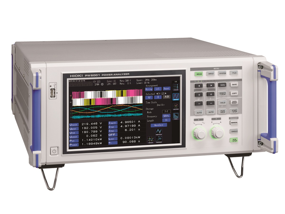
The PW6001 is Hioki’s flagship power analyzer, featuring high accuracy, wide band, and high stability for measuring electrical power from DC to inverter frequencies, providing maximum of 12 channels* to support single- and three-phase inverter motor system measurements and next generation devices such as silicon-carbide (SiC) inverters.
*When synchronizing two 6-channel models connected via optical link.
Features
- Exclusive current sensor phase shift function lets you maintain accuracy even in high frequency, low power factor applications
- Basic accuracy of ±0.02%*1 for power measurement *1 PW6001 accuracy only. Instrument delivers accuracy of ±0.07% even after the current sensor accuracy has been added.
- High noise resistance and stability (80 dB/100 kHz CMRR, ±0.01%/°C temperature characteristics)
- Accurate measurement even when the load is characterized by large fluctuations; TrueHD 18-bit resolution
- 10 ms data refresh while maintaining maximum accuracy (using a specially designed IC to make all measurements independently while performing simultaneous calculations.)
- DC accuracy of ±0.07%, which is key for stable, accurate efficiency measurement
- Wide frequency bandwidth of DC, or 0.1 Hz to 2 MHz
- Achieve true frequency analysis with high-speed 5MS/s sampling (18 bit)
- Synchronize 2 units for up to 12 channels*2 in real time *2 Two 6-channel models can be connected with an optical connection cable
- Special triggers to enable waveform analysis and motor analysis without the need for an oscilloscope
- Wideband harmonic analysis up to the 100th order with a 1.5 MHz band
- Send measured values to HIOKI data loggers using a Bluetooth® wireless technology compatible adapter (LR8410 Link-compatible products), Ver. 2.0 and later
Applications
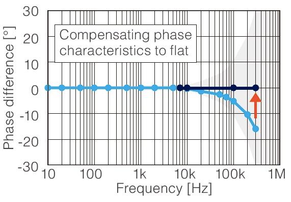 CURRENT SENSOR PHASE SHIFT
Current sensor phase shift is essential especially in high current situations in order to achieve optimal measurement precision. Current sensors typically exhibit gradually increasing phase error in the high-frequency region due to the characteristics of the sensor’s magnetic core and circuitry. Furthermore, differences in the design of various sensor models cause the magnitude of this error to vary. The PW6001’s current sensor phase shift function uses sensor-specific phase error information to correct for error, thereby improving phase characteristics in the high-frequency region and reducing power measurement error. Phase shift correction is conducted with a 0.01° resolution in order to measure power even more accurately.
0.1 HZ TO 2 MHZ FREQUENCY BANDWIDTH
Power measurements across wide bandwidths are required for supporting high-speed switching devices such as SiC. Compared even to the Hioki 3390 Power Analyzer, the PW6001 is engineered with 10x the frequency band and sampling performance. High accuracy, wideband, and high stability. The Hioki PW6001 combines the 3 important elements of power measurement and basic performance backed by advanced technology to achieve unsurpassed power analysis.
HIGH-SPEED SAMPLING OF 5 MS/S FOR TRUE FREQUENCY ANALYSIS
Measurements based on sampling theorem are required to perform an accurate power analysis of PWM waveforms. The Hioki PW6001 features direct sampling of input signals at 5 MS/s, resulting in a measurement band of 2 MHz. This enables analysis without aliasing error
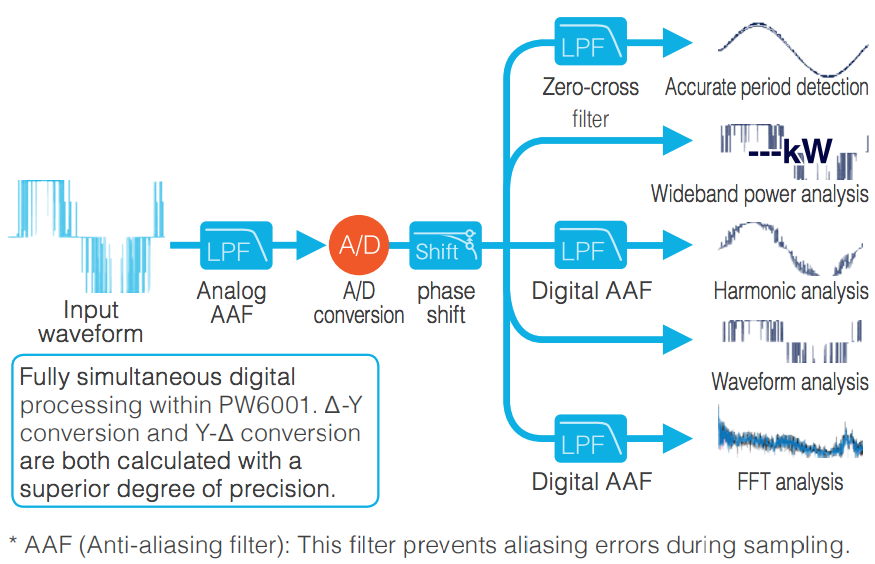
FAST, SIMULTANEOUS CALCULATION FUNCTIONS ACHIEVED WITH POWER ANALYSIS ENGINE II
All measurements, including period detection, wideband power analysis, harmonic analysis, and waveform analysis, are digitally processed independently and with no effect on each other. Fast calculation processing is used to achieve a data update speed of 10 ms while maintaining maximum accuracy.
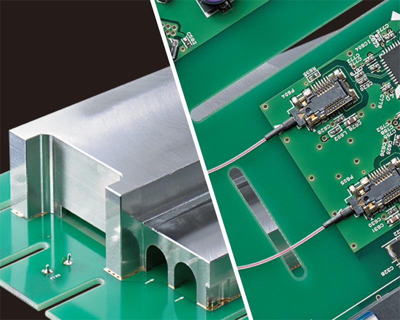
STRENGTHENED RESISTANCE TO NOISE AND TEMPERATURE FLUCTUATIONS IN THE ABSOLUTE PURSUIT OF MEASUREMENT STABILITY
The custom-shaped solid shield made completely of finely finished metal and optical isolation devices used to maintain sufficient creepage distance from the input terminals dramatically improve noise resistance, provide optimal stability, and achieve a CMRR performance of 80 dB/100 kHz. Add the superior temperature characteristics of ±0.01%/°C and you now have access to a power analyzer that delivers top-of-the-line measurement stability.
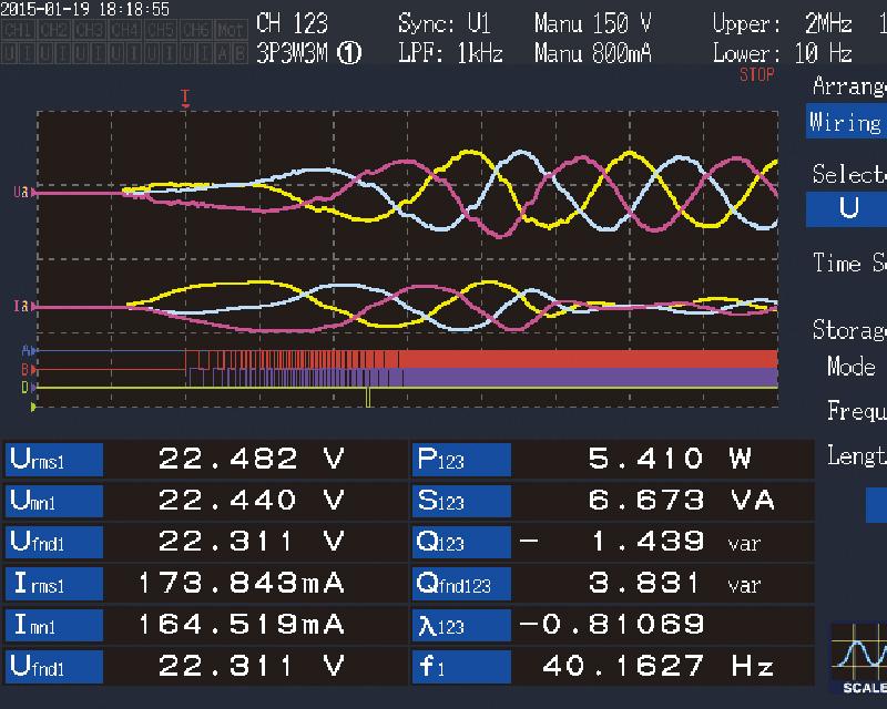
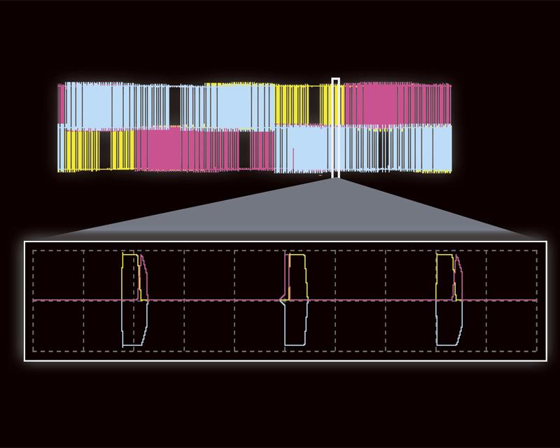
ANALYZE WAVEFORMS WITHOUT AN OSCILLOSCOPE
In addition to voltage and current waveforms, torque sensor and encoder signals can also be displayed simultaneously. The PW6001 is also built in with triggers, pre-triggers, other triggers convenient for motor analysis such as for PWM waveforms, as well as encoder pulse triggers.
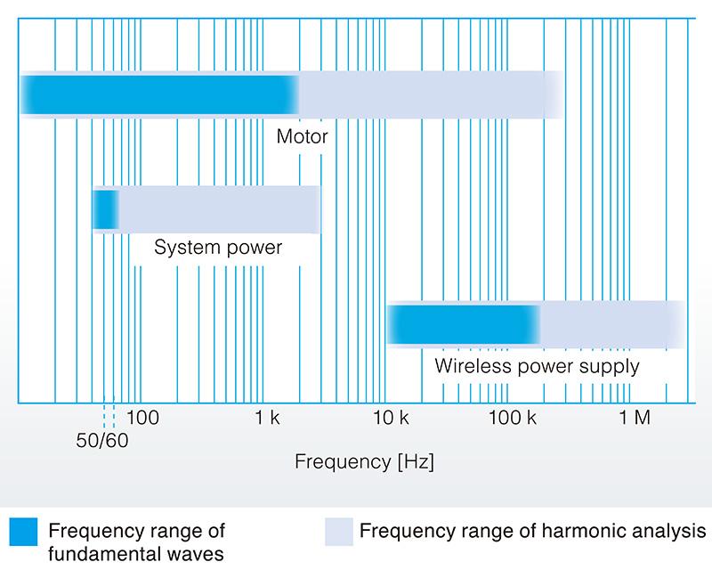
HARMONIC ANALYSIS UP TO 1.5 MHZ
Wideband harmonic analysis is provided as a standard feature to a max. 100th order for fundamental frequencies 0.1 Hz to 300 kHz and an analysis band of 1.5 MHz. Analysis of fundamental waves in motors and measurement of distortion rate in the transmission waveforms for wireless power supplies are now possible.
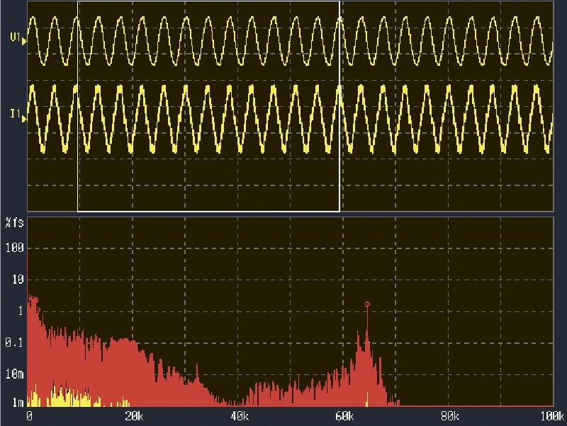
FFT ANALYSIS OF TARGET WAVEFORMS
Frequency analysis up to 2 MHz. Specify any waveform analysis range you like and see the 10 highest peak values and frequencies displayed.
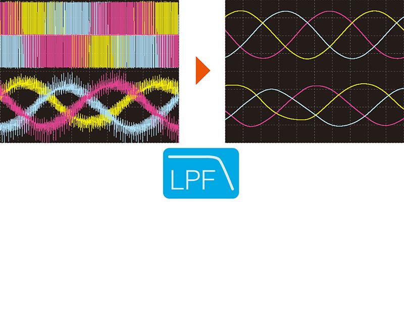
DIGITAL LPF FOR DISPLAYING THE WAVEFORM YOU WANT TO VIEW
Select a cutoff frequency for the measurement target. Digital LPF greatly reduces noise to let you display the waveform you want to view.
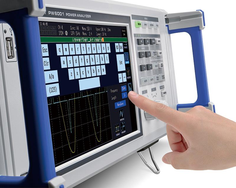
SEAMLESS OPERABILITY
Time spent on operations is reduced, to allow focused concentration on analysis. -9-inch touch screen with soft keypad -Dual knobs for vertical/horizontal manipulation of waveforms -Wiring confirmation function, to avoid wiring mistakes -Enter handwritten memos on the screen, or use the onscreen keypad
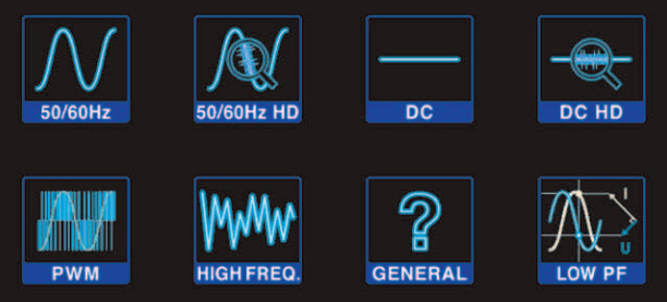
ONE-TOUCH SETTINGS TAKE YOU TO MEASUREMENT IMMEDIATELY
The built-in easy setup function allows you to simply select the type of measurement line and immediately start measurement using the automated optimum settings.
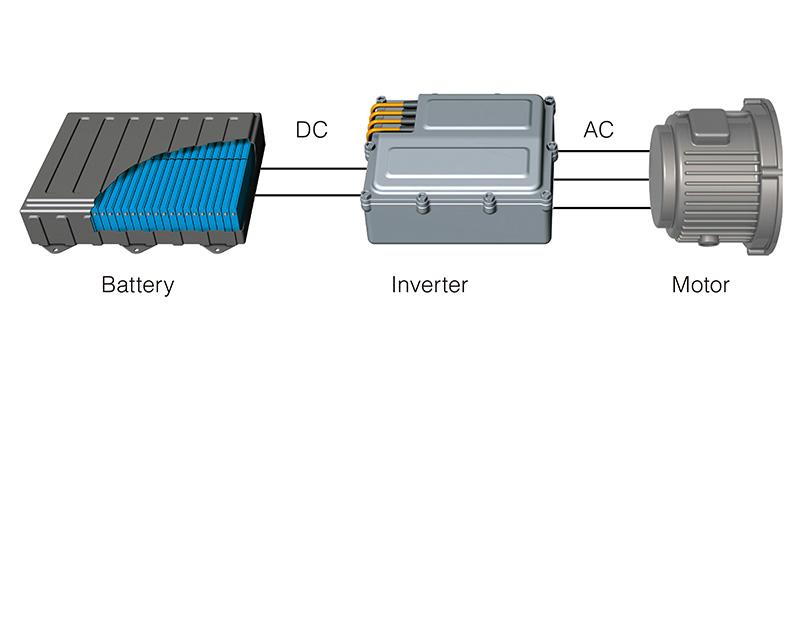
DC ACCURACY IS INDISPENSABLE FOR ACHIEVING CORRECT EFFICIENCY MEASUREMENTS
For example, when measuring the efficiency of a DC/AC converter, not only AC accuracy but also DC accuracy are equally important. With the PW6001, a DC measurement accuracy of ±0.02% rdg. ±0.05% f.s.* delivers correct and stable efficiency measurements. *Unit accuracy only
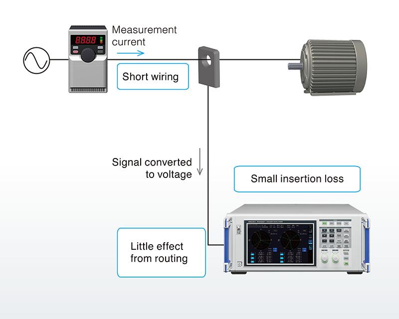
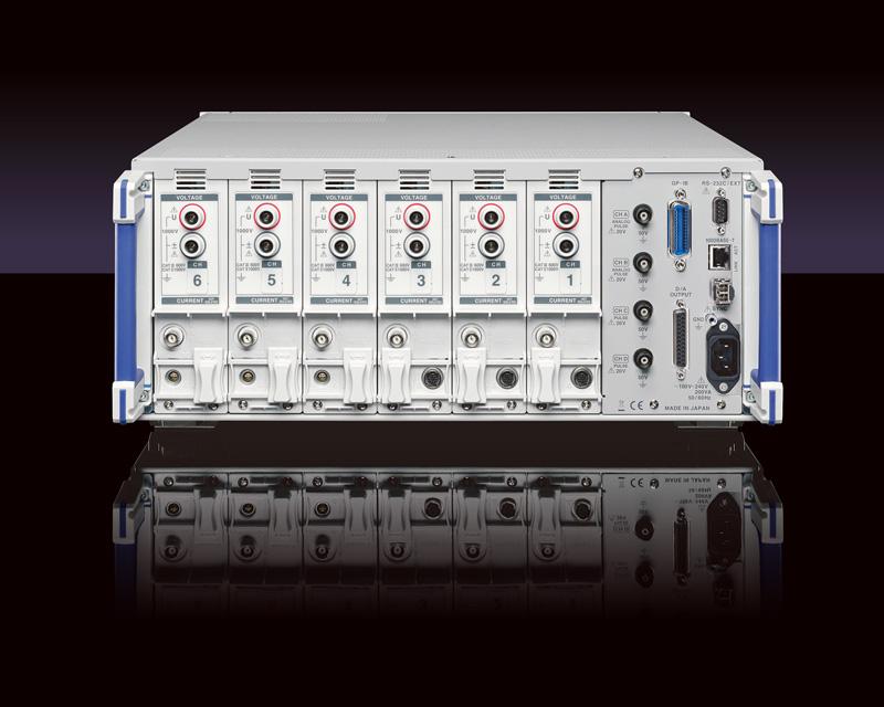
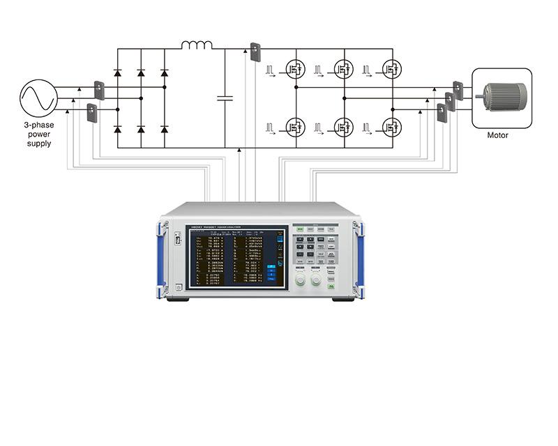
SPECIALLY DESIGNED FOR CURRENT SENSORS TO ACHIEVE HIGHLY PRECISE MEASUREMENT
This reduces the effects of wiring and meter loss, allowing measurements with wiring conditions that are close to the actual operating environment for a highly efficient system. – Short wiring – Little effect from routing – Small insertion loss

HIGH-ACCURACY CLAMP CURRENT SENSOR
The CT684x series feature broad temperature characteristics and an operating temperature range of -40°C to 85°C, allowing them to be used in operational evaluations of devices and inside equipment that are subject to extreme temperature changes. The current sensors’ tough performance helps ensure you can make the measurements you need.
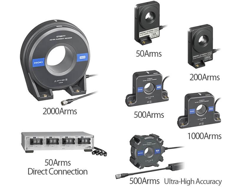
GET A COMBINED ACCURACY OF ±0.075% RDG. WITH CURRENT BOX PW9100
Add ±0.05% rdg. accuracy of the current sensor to the PW6001’s basic accuracy of ±0.025% rdg. to achieve accuracy of ±0.075%. Choose from a diverse array of sensors to cover very small currents from 10mA up to large 2000A* loads. *Effective measurement range.
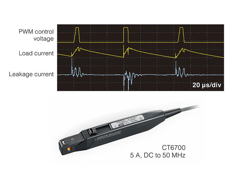
WIDEBAND CURRENT PROBES SUPPORTED
When combined with the HIOKI wideband current probes, it is also possible to measure minute currents of 0.5 mA. This is perfect for observing leakage current waveforms in inverters. ・CT6700、CT6701 1mA〜 ・CT6710、CT6711 0.5mA〜
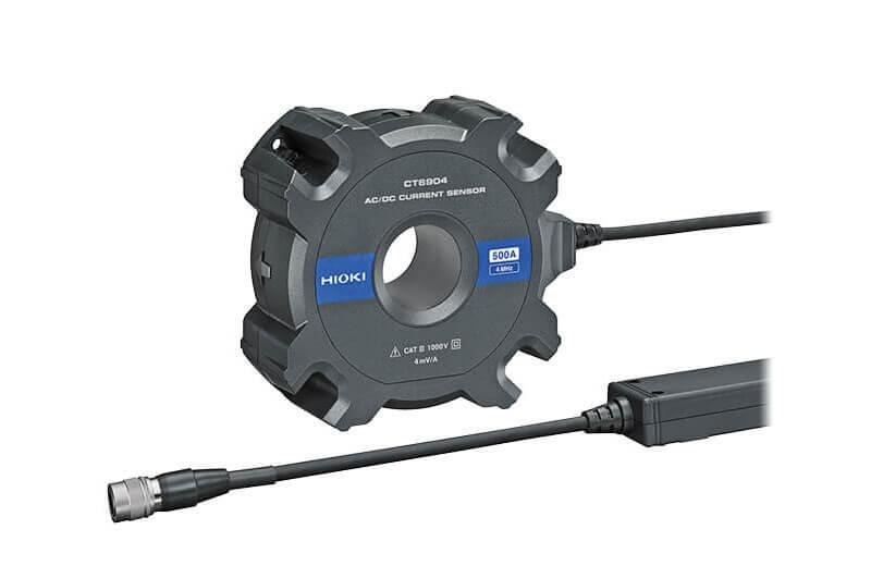
CT6904, THE OPTIMAL DEVICE FOR TESTING LARGE CURRENT INVERTERS
Newly developed opposed split coil technology is used in winding (CT) areas, achieving a wide measurement range from DC to 4MHz. The CT6904 makes it a world-class current sensor that provides the ultimate level of performance when used in conjunction with the Power Analyzer PW6001. (The sensor is also available in an 800A rated version.)
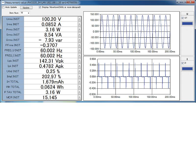
PC COMMUNICATION SOFTWARE – PW COMMUNICATOR
PW Communicator is an dedicated application software for communicating between a PW6001 power meter and a PC. Free download is available from the Hioki website. The application contains convenient functions for setting the PW6001, monitoring the measurement values, acquiring data via communication, computing efficiency, and much more.

REMOTE CONTROL VIA LAN
Control the PW6001 remotely from a tablet, smartphone, or any device offering a standard web browser.
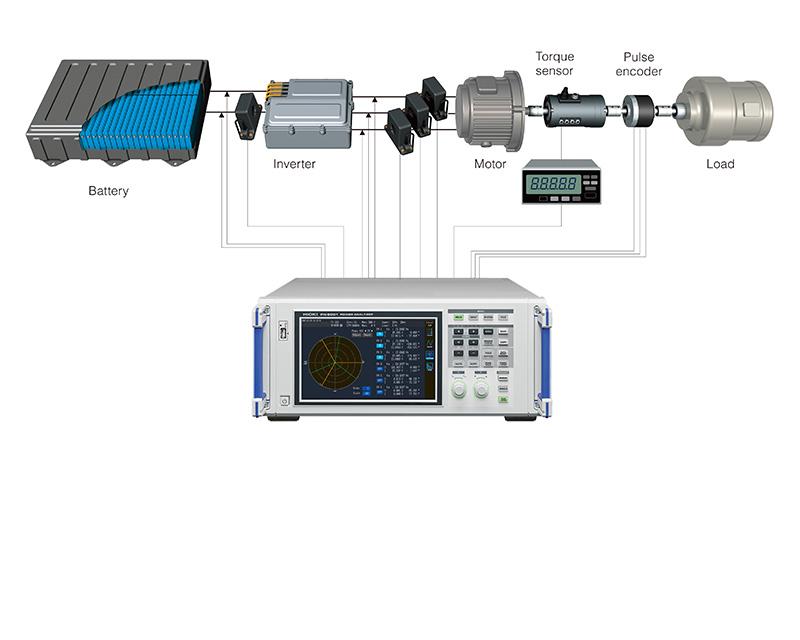
DIVERSE MOTOR ANALYSIS FUNCTIONS
Enter signals from torque meters and speed meters to measure motor power. In addition to motor parameters such as motor power and electrical angle, output signals from insolation meters and wind speed meters can also be measured.
SIC MEASUREMENT ACHIEVED WITH HIGH RESOLUTION
High resolution is required for the high precision measurement of PWM waveforms for SiC semiconductors with low ON resistance. TrueHD 18-bit is achieved at a level of precision that has never been seen before.
ADVANCED ELECTRICAL ANGLE MEASUREMENT FUNCTION
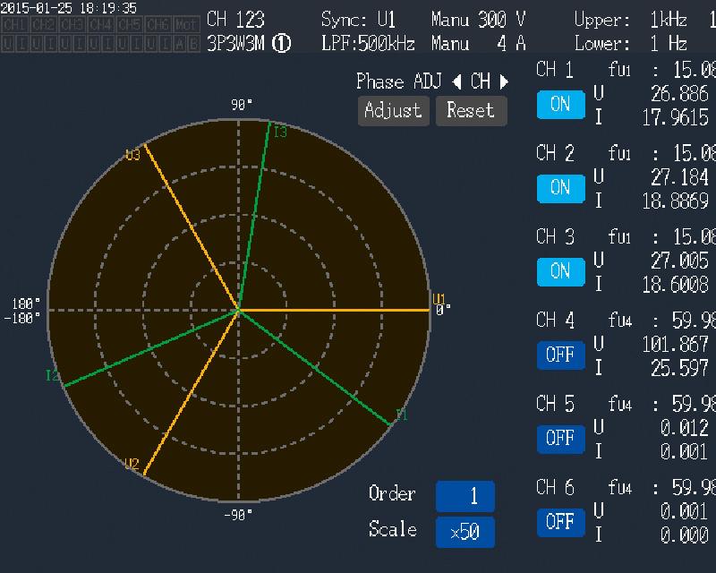
The PW6001 features a built-in electric angle measurement function required for the measurement of motor parameters in high-efficiency synchronized motors and the analysis of vector control via dq coordinate systems. Make real-time measurements of phases for voltage and current fundamental wave components based on encoder pulses. Further, zero-adjustment of the phase angle when induced voltage occurs allows phase measurement at the induction voltage standard. Finally, the PW6001 can detect the forward/reverse from A phase and B phase pulses to enable 4-quadrant analysis of torque and RPM.
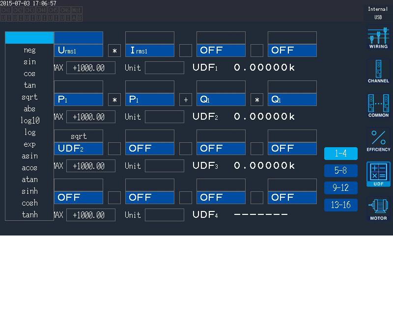
DISPLAY ANY CALCULATION RESULT IN REAL-TIME
Set equations to have PW6001 compute measurement values in the way you want. You can enter up to 16 calculation formulas, and functions like sin and log are supported. Calculation results can be used as parameters for other calculation formulas, enabling complex analysis. -Calculate Ld and Lq in motor vector control -Measure ferrite core loss -Add up RMS and power -Calculate multisystem efficiency and loss with solar power modules and similar equipment
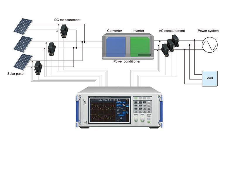
POWER CONDITIONER TESTING
Parameters required for power conditioners, such as fundamental wave reactive power Qf nd, DC ripple rate, and 3-phase unbalanced rate, can be measured and displayed simultaneously. The required measurement data can be viewed at a glance, improving test efficiency.
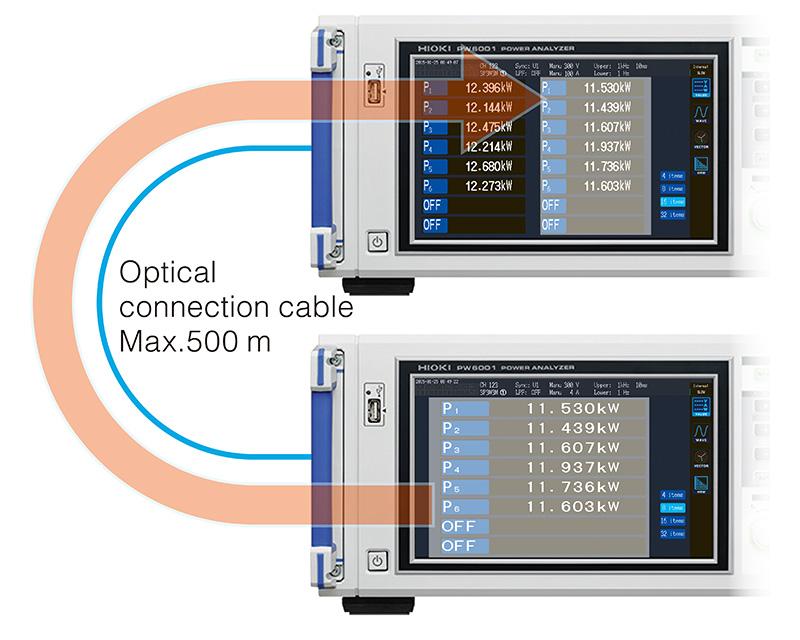
BUILD A 12-CHANNEL POWER METER USING “NUMERICAL SYNCHRONIZATION”
For multi-point measurements, use the numerical synchronization function to transfer power parameters from the slave device to aggregate at the master in real-time, essentially enabling you to build a 12-channel power analysis system
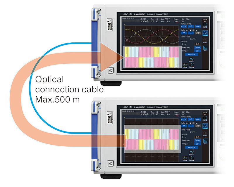
SIMPLY TRANSFER WAVEFORMS WITH “WAVEFORM SYNCHRONIZATION”
Achieve real-time* transfer of 5 MS/s 18-bit sampling data. Measurement waveforms on the slave instrument are displayed without modification on the master unit, paving the way for new applications for power analyzers, such as measurement of the voltage phase difference between two separate devices. * For both master instruments and slave instrument, waveform synchronization operates only when there are 3 or more channels. Max. ±5 sampling error
HIOKI POWER ANALYZER PW6001
![]()
To view the pdf files, the Adobe Reader from Adobe Systems is required.