This website uses cookies so that we can provide you with the best user experience possible. Cookie information is stored in your browser and performs functions such as recognising you when you return to our website and helping our team to understand which sections of the website you find most interesting and useful.

ITEMLIST
Products Infomation

- Products by Category
- Automotive&EV
- Motor Coil Testers
- HIOKI PARTIAL DISCHARGE DETECTOR ST4200
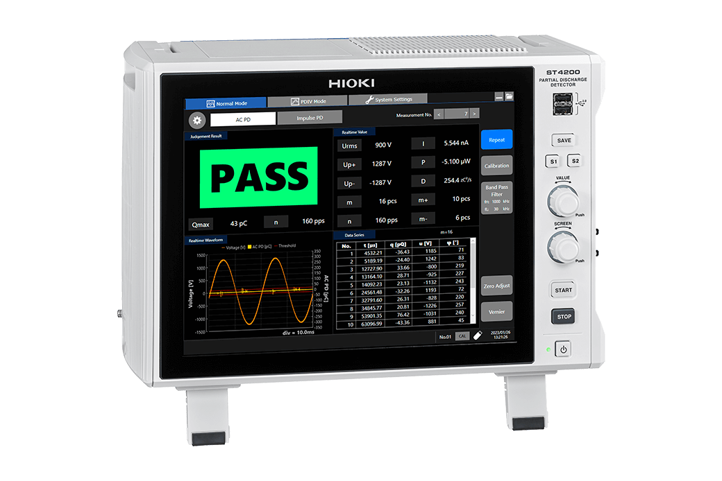
HIOKI PARTIAL DISCHARGE DETECTOR ST4200
U.S.-based sales, and delivery available.
The ST4200 Partial Discharge Detector excels in detecting high-frequency noise in EV motors, crucial due to high-voltage switching in SiC/GaN semiconductors. It supports dual PD tests for in-depth insulation defect analysis and integrates seamlessly with SW2001 Multiplexer to streamline setups and enhance noise resistance. This approach minimizes EMI and ground loop interference, ensuring precise measurements. Ideal for detecting subtle motor defects with improved accuracy.
Key Features
・Dual-mode PD detection: AC PD and surge PD detection
・Noise-resistance through high-frequency CT
・Compatible with the SW2001 High Voltage Multiplexer
Features
Maximize the detection of latent failures
-Dual-mode PD detection
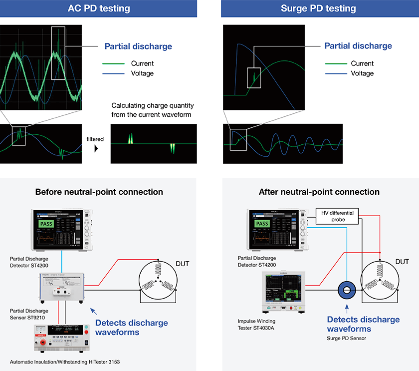
Discover latent insulation defects in motor windings with the AC PD test (IEC 60270 and IEC 60034-27-1 compliant) and surge PD test (IEC 61934 Ed. 2 and IEC60034-27-5 compliant). The ability to select between the two types of PD tests allows you to customize your inspection process to the specific needs of each motor, maximizing the detection of latent failures.
Reliable PD testing even on the production line
-Noise-resistant PD detection with a high-frequency CT
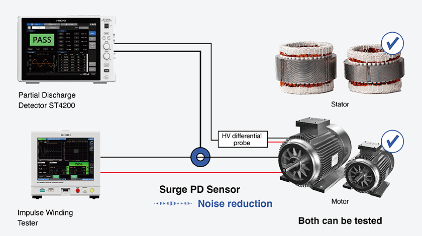
Partial discharge testing on production lines with a microwave antenna is highly susceptible to noise interference. Using a high-frequency CT minimizes noise, simplifies installation by reducing the need for precise positioning, and thus prevents measurement errors. Unlike the antenna method which cannot detect partial discharges through the finished motor casing, this method also allows surge PD testing for finished motors.
Simplified system design for reduced noise impact
-Integration with the SW2001 High Voltage Multiplexer
Complex testing environments often come with high noise which are difficult to reduce. The ST4200 Partial Discharge Detector’s high noise resistance can be further minimized by integrating with the SW2001’s multiplexer-based architecture. This design significantly reduces wiring complexity by consolidating multiple input signals, minimizing cable runs and interconnections. This approach effectively reduces potential noise sources such as electromagnetic interference (EMI), ground loops, and capacitive coupling, resulting in more accurate and reliable measurements.
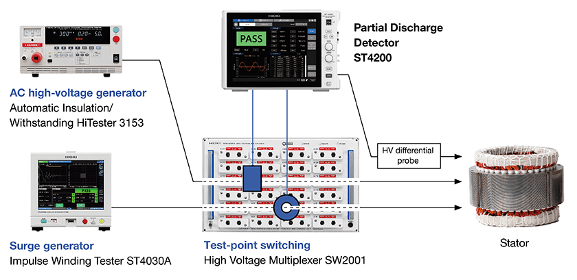
Basic setup for partial discharge testing:
1. Partial Discharge Detector ST4200
2. Automatic Insulation/Withstanding HiTester 3153 as an AC high-voltage power supply
3. Impulse Winding Tester ST4030A as an Impulse power supply
4. High Voltage Multiplexer SW2001 for switching between test points
5. Partial discharge sensor for AC PD testing *1
6. Partial discharge sensor for surge PD testing *1
*1:These sensors are built into the SW2001. Please specify at time of order as the component is embedded during the manufacturing process.
Specifications
AC PD measurement
| Detection method | Discharge charge-quantity measurement method using detected impedance and a band-pass filter in compliance with IEC 60270 and IEC 60034-27-1 |
| Test frequency range (applied voltage) |
45 Hz to 1.1 kHz |
| Charge quantity measurement range | 10 pC ≤ Q ≤ 500 pC (test piece capacitance C: 200 pF ≤ C < 2 nF) 10 pC ≤ Q ≤ 2500 pC (test piece capacitance C: 2 nF ≤ C ≤ 10 nF) |
| Measurement parameters | [Normal mode] Maximum repeating PD strength (Q max), PD pulse count (m, m+, m-), PD pulse incidence (n), voltage RMS value (U rms), voltage crest value (Up+, Up-), average discharge current (I), discharge power (P), second-order rate (D), PD pulse apparent charge (q), PD pulse phase angle (φ)[PDIV mode] (normal mode parameters plus the following) PD inception voltage (Ui), PD extinction voltage (Ue) |
Impulse PD (surge PD) measurement
| Detection method | Discharge current detection using a CT and digital filter in compliance with IEC 61934 Edition 2.0 and IEC 60034-27-5 |
| Sampling rate | 200 MS/s |
| Measurement parameters | [Normal mode] PD peak discharge magnitude (Qpk), pulse sequence PD count (m)[PDIV mode] (normal mode parameters plus the following) PD inception voltage (PDIV), repetitive PD inception voltage (RPDIV), repetitive PD extinction voltage (RPDEV), PD extinction voltage (PDEV), repeating PD peak discharge magnitude (RQpk) |
High-voltage source control
| Control description | Cooperative control of withstanding voltage tester and impulse winding tester used as high-voltage generators for partial discharge testing |
| Compatible instruments (as of Feb. 2025) | Automatic Insulation/Withstanding HiTester 3153, Impulse Winding Tester ST4030A, etc |
Specifications shared by AC PD and impulse PD (surge PD) measurement
| Functions | Graph display function, judgment function |
| Save destination | SD memory card, USB drive, SSD (Use only storage media sold by Hioki.) |
| Effects of radiative radio frequency electromagnetic fields | 50 pC or less (at 10 V/m) |
| Effects of conductive radio frequency electromagnetic fields | 50 pC or less (at 10 V) |
| Effects of pulse noise superposed on power supply | 50 pC or less (with pulse noise of 1 kV and pulse width of 50 ns) |
| Interfaces | LAN, USB, RS-232C* (please use a commercially available USB-serial conversion cable.), monitor output, EXT. I/O (measurement start, measurement cancel, overall judgment PASS, overall judgment FAIL) *For connecting to secondary instruments (e.g., Automatic Insulation/Withstanding HiTester 3153) |
| Power supply | Rated supply voltage: 100 to 240 V AC; rated power: 300 VA |
| External dimensions | Approx. 353 mm (13.9 in.) W × 235 mm (9.25 in.) H × 154.8 mm (6.09 in.) D (excluding protruding parts) |
| Mass | Approx. 7.3 kg (257.5 oz.) (with U8332); approx. 7.1 kg (250.4 oz.) (without U8332) |
| Included accessories | Power cord × 1, operating precautions × 1, startup guide × 1 |
![]()
To view the pdf files, the Adobe Reader from Adobe Systems is required.