This website uses cookies so that we can provide you with the best user experience possible. Cookie information is stored in your browser and performs functions such as recognising you when you return to our website and helping our team to understand which sections of the website you find most interesting and useful.

ITEMLIST
Products Infomation

- Products by Category
- Automotive&EV
- Motor Coil Testers
- HIOKI Impulse Winding Tester ST4030A
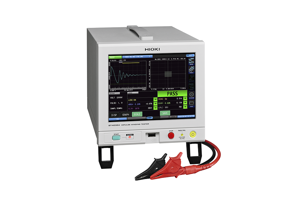
HIOKI Impulse Winding Tester ST4030A
U.S.-based sales, and delivery available.
The Hioki ST4030A impulse winding tester diagnoses rotor windings by quantifying response waveforms, crucial for electric vehicle motors. It detects layer shorts and single-turn faults using pass/fail plots based on master waveform comparisons. This surge tester integrates resistance and insulation-testing functions. Employing Hioki's original filtering minimizes noise, ensuring precise detection even in challenging conditions. Max voltage: 3300-4200 V AC.
Optional function for the ST4030A
DISCHARGE DETECTION UPGRADE ST9000
- Optional function for the ST4030A Impulse Winding Tester to detect microscopic partial discharges obscured by noise. Detect pseudo-shorts with high accuracy
Key Features
・Identify previously undetectable defects
・Detect waveforms with high precision (200 MHz high speed sampling × high 12-bit resolution)
・Identify single-fault turns via quantification of response waveforms into LC and RC values
・Diagnose defective insulation (pseudo-shorts) between motor windings by testing for microscopic partial discharges hidden in noise (option)
How to Use the Hioki Impulse Winding Tester ST4030A
The ST4030A detects the existence of layer shorts between coil windings, defects that are found in motor inductors. By using a master waveform taken from a reference coil after applying an impulse voltage, and comparing it to the measured waveform across a specific interval of the coil under test, the resulting area difference can help determine pass or fail easily and accurately. In addition, quantification of response waveforms, a new method developed by Hioki, lets you detect even single-turn faults by using a pass/fail distribution plot. Watch this video to learn how to easily make settings and begin testing right away.
Specifications
Accuracy guaranteed: 1 year
| Measurement items | • Quantification (LC value, RC value) of the response waveform obtained when impulse voltage is applied, pass / fail judgment • Waveform judgment using AREA value, Flutter, Laplacian etc. • Equipped with dielectric breakdown voltage test function |
|||||
| Applied voltage | 100 V to 4200 V (Setting resolution: 10 V steps) Maximum applied energy: approx. 88 mJ |
|||||
| Testable inductance range | 10 μH to 100 mH | |||||
| Sampling | 200 M / 100 M / 50 M / 20 M / 10 MHz, Resolution: 12 bits, Number of data: 1001 to 800 points (1000 point steps) | |||||
| Voltage detection accuracy | [DC accuracy] ± 5% of setting, [AC band] 100 kHz: ± 1 dB | |||||
| Determination method | LC · RC value judgment, waveform judgment, discharge judgment (when incorporating the ST9000) | |||||
| Number of test condition tables | 255 (test condition setting, judgment condition setting, master waveform) | |||||
| Test time | About 60 ms (3000 V, 1 pulse, reference value at decision OFF) | |||||
| Display | 8.4-inch SVGA color TFT liquid crystal (800 × 600 dots), touch panel | |||||
| Interface | Standard: EXT.I/O, USB host (memory), USB device (communication), LAN Optional: RS-232C (Z3001), GP-IB (Z3000) |
|||||
| Power supply | 100 V to 240 V AC, 50/60 Hz, 80 VA max. | |||||
| Dimensions and mass | 215 mm (8.46 in)W × 200 mm (7.87 in)H × 348 mm (13.7 in)D, 6.7 kg (236.3 oz) | |||||
| Included accessories | Power cord ×1, Instruction Manual ×1, Application disc ×1, Usage notes ×1 | |||||
![]()
To view the pdf files, the Adobe Reader from Adobe Systems is required.