This website uses cookies so that we can provide you with the best user experience possible. Cookie information is stored in your browser and performs functions such as recognising you when you return to our website and helping our team to understand which sections of the website you find most interesting and useful.

ITEMLIST
Products Infomation

- Products by Category
- Automotive&EV
- ECG KOKUSAI – DWIT-05 Series
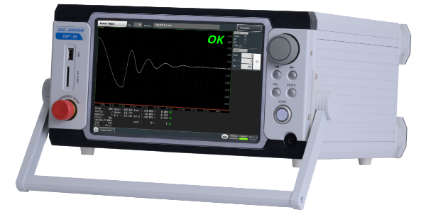
Detect Defects Faster – Reliable Coil Testing for Modern QA Teams
[Contact Us]
● High-speed, high-accuracy multi-mode testing
● Compact, easy-to-use design with barcode support
● Partial Discharge (PD) detection option for insulation issues
The DWIT series from ECG KOKUSAI builds on the DWX series' legacy, providing precise impulse winding testers with enhanced performance and reliability. It boasts high accuracy and diverse functions, including improved operability and comprehensive communication interfaces.
These testers efficiently assess winding quality through nondestructive tests, detecting defects and evaluating degradation over time. The system stores 1000 test results, assisting in consistent quality control.
High-Performance Features for Reliable Coil & Motor QA
High-Resolution, High-Speed Waveform Capture
12-bit resolution × 300 MHz sampling ADC enables precise acquisition of detailed waveforms.
Up to 16,384 data points ensure waveform disturbances and partial discharge noise are captured, with zoom display available after testing.
A built-in cursor function allows verification of waveform rise time, pulse width, and peak voltage.
Database-Driven Inspection Process Visualization
The built-in database stores master waveforms, test conditions, and results — including both waveforms and judgment values.
SQL client software enables remote browsing from a computer.
Search results by pass/fail or date/time help analyze trends such as NG (No Good) generation rates.
Flexible Additional Options
PD (Partial Discharge) detection antenna, 3ch + GND built-in switching circuit, 4-terminal measurement circuit, additional applied energy, current measurement, and more are available.
(*Some options cannot be installed simultaneously.)
User-Friendly Operation
A 10.1-inch color TFT LCD touch panel provides intuitive operation.
External USB or SD memory supports easy storage of screenshots.
Master waveforms can be created using averaging, composite, or test waveform data.
Overview – High-Precision Impulse Winding Tester for Coil & Motor QA
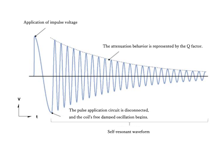
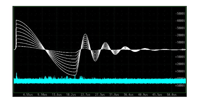
The impulse winding tester efficiently and nondestructively performs electrical tests on coils in their wound state.
The test principle is to apply an impulse voltage to a reference winding (master coil) and a winding under test, then compare the transient waveforms to determine pass or fail.
These transient (damped vibration) waveforms reflect parameters such as inductance, Q values, coil turns, layer shorts, and core material differences. By applying a high impulse voltage, insulation defects can also be detected from corona discharge events.
In short, most of the characteristics required for winding quality assurance can be tested in a very short time.
New mode of DWIT-05
Aging Test (Continuous Printing) Mode
Allows continuous application of impulse voltage for a set duration or number of cycles.
Used to evaluate sample degradation under prolonged impulse voltage application.
When an optional partial discharge (PD) sensor is added, the time or cycle count until discharge occurs can be recorded.
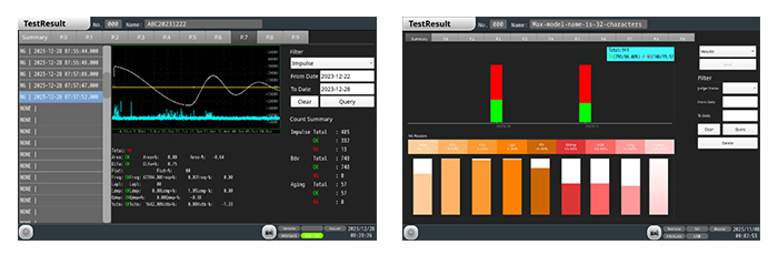
Test Result Mode
Test results are stored in the unit’s memory.
The system displays OK/NG counts as graphs and values, and retains the last 1,000 test screens for review.
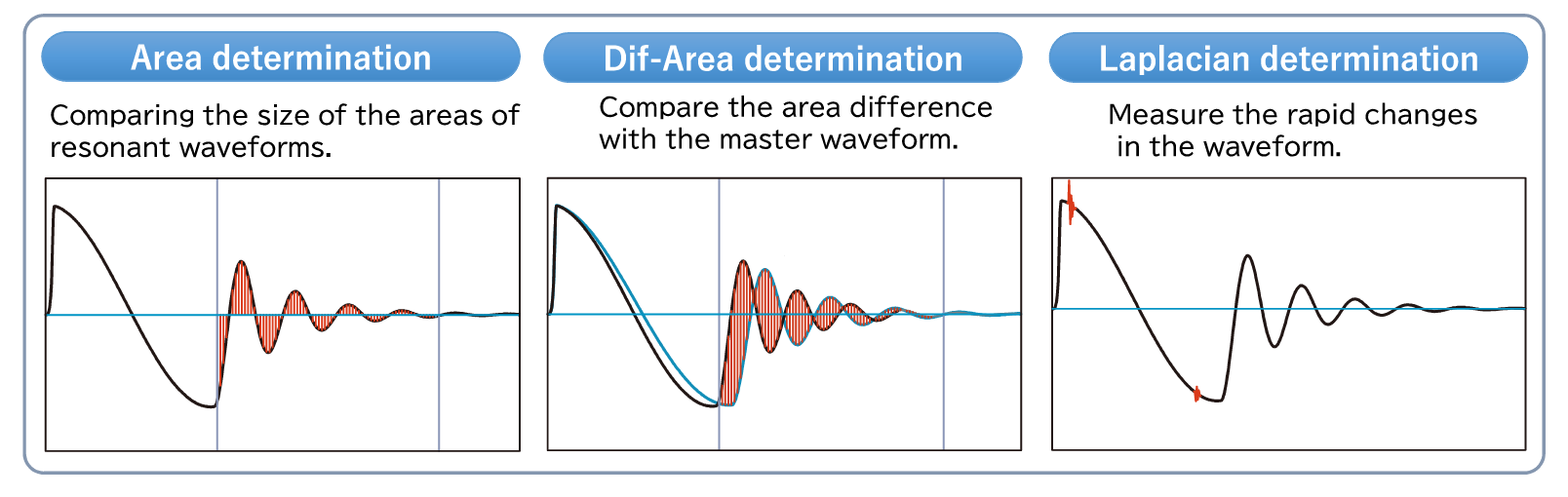
Existing determination items
Enhanced resolution, higher sampling frequency, and increased sample count enable more detailed coil QA measurements.
Break Down Voltage Test
The BDV mode automatically increases applied voltage to identify the breakdown voltage.
This is included as a standard feature.
New Measurement Indicators
Introducing a new indicator of the characteristics of the test object, measurement of actual values
1. Frequency Judgment – Resonance Frequency
Calculates the frequency from the average cycles of self-resonant waveforms.
Frequency changes may indicate variations in impedance, capacitance, or losses.
2. Logarithmic Decrement Judgment – Attenuation Rate
Measures waveform amplitude and calculates the logarithmic decrement from the average.
Attenuation changes may result from inductance, capacitance, or loss variations.
3. Peak Stability Judgment – Peak Voltage (V)
Measures amplitude from the peak voltage of the self-resonant waveform.
Variations can reflect waveform distortion or disturbances caused by discharge, indicating losses in the test object.
Specifications
| Applied voltage ・ Energy | 100-5000V・0.12J | |
| Voltage accuracy | ±5.0% | |
| Applied step | 1V | |
| Inductance range | 5μ-1H | |
| Resolution / Sampling speed | 12bit / Max. 300MHz (20 steps) | |
| Sampling data | 16384 , 8192 , 4096 , 2048 , 1024 , 512 | |
| Screen display | 10.1” color TFT LCD (1280 x 800 (WXGA)) Touch panel | |
| Test mode | Impulse Test, BDV(PDIV) Test, Aging Test(NEW) | |
| Judgment Item | Existing judgment | Area (area comparison), Dif-Area (waveform difference comparison), Flutter (discharge volume comparison), Laplacian (discharge volume comparison) |
| New Judgment (NEW) | Pkstb(peak voltage), Freq(resonant frequency), Ldec(logarithmic decay rate) | |
| Partial discharge judgment*Option | – | |
| Safety protection function | Emergency stop button, Interlock | |
| Internal memory | Master waveform 1000 models (100 models/10 pages), test results, voltage waveform (csv), screenshot (png) | |
| External interface | RS-232C (max. 115,200 bps) Control(NPN/PNP transistor (changeover by wiring), D-sub 37pin) Ethernet communication (1000BASE-T), protocol (UDP/IP, TCP/IP) USB2.0 host (max. 3Mbps) Trigger output (impulse voltage applied synchronous signal output) |
|
| External storage | USB memory (2 ports), SD card, SDHC card (max. 32GB) | |
| Operating environment | 0°C to 40°C, 80%RH (no condensation) | |
| Input power supply | AC100 ~ 240V, 50Hz/60Hz | |
| Dimensions ・ Weight | 342(W)×188(H)×366(D) (*Excluding protruding parts *in mm) ・ Approx. 9.8kg | |
| Accessories | Test cable, Power cable (A type, with 3-pin adapter), Fuse, Operation manual, Test report | |
Additional option
| 3ch + GND switching circuit | Built-in test circuit switching for 3-phase coil U, V, W, and GND can be set as desired. Compatible with IEC standard recommended circuit testing. In preparation |
| Partial discharge detection circuit | – |
| 4-terminal test circuit | Separates the voltage application and measurement circuits to more accurately measure the voltage at both ends of the coil. |
| Charging capacitor change | The capacity of the charging capacitor has been doubled, increasing output energy and providing countermeasures for samples that are difficult to apply voltage to. |
| Carry Handle | Used for carrying and placing the instrument face up (not included as standard). (Not included as standard.) |
| Rack Mount | Can be mounted on a 19-inch rack. |
![]()
To view the pdf files, the Adobe Reader from Adobe Systems is required.