This website uses cookies so that we can provide you with the best user experience possible. Cookie information is stored in your browser and performs functions such as recognising you when you return to our website and helping our team to understand which sections of the website you find most interesting and useful.

ITEMLIST
Products Infomation

- Products by Category
- Electronic Measuring Instruments
- Recording Meters / Data Loggers / Recorders
- ATSENSE TFW-200/TFM-200
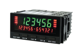
Twin Digital Flow Meter TFW/TFM-200
[Contact Us]
The ATSENSE TFW-200 and TFM-200 are high-performance twin digital panel meters designed for engine R&D and test systems.
The TFW-200 measures both instantaneous and total fuel flow, while the TFM-200 provides dual-channel instantaneous flow measurement with A/B sensor support. Featuring a two-level LCD, CAN output, and a wide range of analog, digital, and communication interfaces (USB, RS-232/485), these meters enable simultaneous measurement, averaging, and repeat integration.
With fast 1 ms analog output, IP66 front protection, and flexible configuration, the TFW/TFM-200 ensures precise and efficient fuel flow monitoring.
Features
- The first panel meter that has been used for CAN data output (option)
- 6-digit and 13-digit, two-level, high brightness LCD display (red and green). You can choose the display color.
- A multitude of options (analog output/BCD output/CAN output/contact output/RS232 communication/RS485 communication/USB communication)
Introduction to Functions
【High-performance functions】
The functions and performance of the flow rate meter have been incorporated into the panel meter. Analog output is at a high speed of 1ms.
And you can choose from a multitude of output options to use
〇 Instantaneous flow and total flow can be measured simultaneously
〇 As well as the real total flow, you can also measure the average flow over any given period
〇 Both flow sensors (A, B) can be measured at the same time, and the display and analog signal for each can be output as desired
〇 The combinations A+B, A-B, and the average flow can also be measured as either the instantaneous or the total flow
〇 An auto-repeat measurement is possible in which integration commences when “Start” is entered, and the display and output refreshed after a set time has elapsed, and this then repeated until “Stop” is entered.
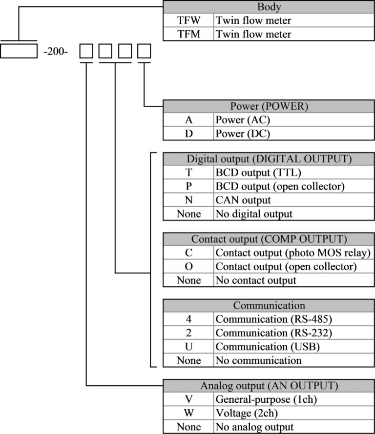
The model configuration of the TFW-200 and TFM-200 is shown in the figure below.
When option “No” was selected the model configuration is left-justified.
Multiple options of the same option group cannot be selected.
Two types of output can be selected from among digital output, contact output, and communication.
Specification
| Model | TFW-200 | TFM-200 | |
| Name | Instantaneous and total flow meter | Instantaneous flow meter | |
| Arithmetic | |||
| Input operations | A/AB (reversible)/A+B/A-B/AB average | ||
| Instantaneous measurement | Measurement method | Periodic calculation method (with function for predicting deceleration) | |
| Measurement clock | 20MHz | ||
| Total measurement | Measurement method | Scaling integration | |
| Integration method | Free/timer stop/timer repeat | ||
| Operation key | 5 points Separate function at measurement/setting | ||
| Memory | Memory element | Non-volatile memory | |
| Memory content | Setting values and total flow | Setting values | |
| Display | |||
| Display | LCD negative, backlight | ||
| Main display | Display items | Instantaneous flow | |
| Display color, character height, number of digits | Switching between red and green backlight, 14.2mm, 6 digits + polarity (-) | ||
| Sub-display | Display items | Total flow (TFW-200 only)/comparator setting values/Instantaneous flow A – B/OFF | |
| Display color, character height, number of digits | Switching between red and green backlight, 6.5mm, 13 digits + polarity (-) at 2 points | ||
| Status display | Display color | Switching between red and green backlight | |
| Instantaneous measurement | Refresh time | 0.1 to 9.9s | |
| Moving average | 1 to 99 | ||
| Signal input (sensor input) | |||
| Number of inputs | 2 inputs | ||
| Types of input signal (CH) | Single-phase (2ch) / UP/DOWN (1ch) / A/B 2-phase signal (1ch) switching | ||
| Maximum input frequency | Single-phase, UP/DOWN signal | 100kHz | |
| A/B 2-phase signal | 60kHz | ||
| Minimum input frequency | 0.005Hz (only for measurement of instantaneous flow) | ||
| Frequency division (pulse average) | Signal A only, 1 to 999 | ||
| Signal input (sensor input) (0) General purpose | |||
| Input level | AC (zero-cross) signal | ±200mV to ±30V, LPF switching | |
| Signal A | |||
| Logic signal | H level 3.9V or more, L level 1V or less (voltage resistance ±30V) | ||
| Others | Pull-up/pull-down switching | ||
| Power supply for sensor | Voltage and maximum current | DC12V±10%, 100mA | |
| External control input | Number of points | 2 points | – |
| Signal type | Contact/TTL (minimum pulse width 5ms) | – | |
| Items | Start/Stop/Reset/Hold switching | – | |
| Analog output | |||
| Refresh time | 0.001 to 9.999s | ||
| D/A conversion | 16bit | ||
| Analog output (V) General purpose (1CH) | |||
| Number of outputs | 1 output | ||
| Output items | Instantaneous flow/total flow | Instantaneous flow | |
| Output range | Voltage output range | ±10/0-10/0-5/1-5 V (load of 4.7kΩ or more) | |
| Current output range | 4-20mA (load of 560Ω or less) | ||
| Accuracy | Voltage output ±0.1%F.S. or less/current output ±0.2% F.S. or less (23℃)/temperature variation ±200ppm/℃ or less | ||
| Analog output (W) Voltage (2CH) | |||
| Number of outputs | 2 outputs | ||
| Output items | Instantaneous flow/total flow | Instantaneous flow | |
| Output range | Voltage output range | ±10V (load of 4.7kΩ or more) | |
| Accuracy | Voltage output ±0.1%F.S. or less (23ºC)/temperature variation ±200ppm/ºC or less | ||
| Contact output (C) Contact output (photo MOS relay), (O) Contact output (open collector) | |||
| Number of outputs | 4 outputs | ||
| Refresh time | Analog synchronization/display synchronization switching | ||
| Output items | Comparator/unit pulse switching | ||
| Unit pulse rate, maximum frequency | 0.1 to 9999.9mL/P, 1kHz | ||
| Output circuit | (C) Photo MOS relay | Maximum load voltage (peak AC/DC) 350V, continuous load current (peak AC/DC) 80mA, output ON resistance 35Ω (typical) | |
| (O) Open collector | NPN open collector, maximum load voltage 30V, maximum load current 15mA | ||
| Communication (4) RS-485 (2) RS-232 (U) USB | |||
| Communication format | Serial communication | (4) RS-485/(2) RS-232/(U) USB | |
| Communication speed | 9.6k/19.2k/38.4k bps | ||
| Data length | 7/8 bit | ||
| Parity bit | Null/even/odd | ||
| Stop bit | 1/2 bit | ||
| Character code | ASCII | ||
| Digital output | |||
| Output items | Instantaneous flow/total flow | Instantaneous flow | |
| Refresh time | Analog synchronization/display synchronization switching | ||
| Digital output (T) BCD output (TTL), (P) BCD output (open collector) | |||
| Number of output digits | 6 digits + polarity | ||
| Output circuit | (T) TTL | Output voltage 0-5V (output current ± 100mA, but ± 4mA/ch) | |
| (P) Open collector | NPN open collector, maximum load voltage 30V, maximum load current 20mA/ch | ||
| Digital output (N) CAN | |||
| Output circuit | CAN2.0B compliance | High-Speed CAN (ISO11898-2) | |
| Communication speed | 1Mbps/500kbps/250kbps/125kbps | ||
| Data format | Little endian/Big endian | ||
| ID length | Standard 11bit/Extended 29bit | ||
| Data format | Signed long (4 bytes) | ||
| Output refresh time | Digital output refresh time/1/2/5/10ms | ||
| General specification | |||
| Supplied power sources | (A) Power supply (AC) | AC100 to 240V ±10% (50/60Hz), (100V, 18VA or less, 240V, 24VA or less) | |
| (D) Power supply (DC) | DC12 to 24V ±10% (10W or less) | ||
| Electrical insulation | Insulation range | Sensor input – analog output – contact output – communication and digital output – supplied power sources | |
| Protective structure | Front panel IP66 | ||
| Operating temperature and humidity range | 0 to 50℃, 85%RH or less (with no condensation) | ||
| External dimensions, Weight | W: 96 H: 48 D: 100 (D: 93 inside part) | ||
| Approx. 230g (when equipped with all options) | |||
![]()
To view the pdf files, the Adobe Reader from Adobe Systems is required.