
This website uses cookies so that we can provide you with the best user experience possible. Cookie information is stored in your browser and performs functions such as recognising you when you return to our website and helping our team to understand which sections of the website you find most interesting and useful.


ITEMLIST
Products Infomation

- Products by Category
- Electronic Measuring Instruments
- Circuit / Element / Parts Evaluation Measuring Instruments
- MICROTEST Impedance Analyzer 6632
Analysis of Impedance of Passive Components/Materials at Different Frequencies.
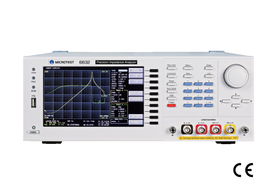
The MICROTEST 6632 Impedance Analyzer offers a wide frequency range of 10Hz to 50MHz for measuring the impedance characteristics of components and materials. The measured parameters include |Z| (impedance), |Y| (admittance), θ (phase angle), X (reactance), R (series/parallel resistance), G (conductance), B (Susceptance), L (inductance), D (dissipation factor), Q (quality factor), DCR (DC resistance), C (capacitance), ESR (equivalent series resistance), ε (relative permittivity), and μr (relative permeability). It supports both Meter mode and Sweep Analysis mode, allowing measurement results to be displayed in numeric or graphical formats. The system can be equipped with the optional Equivalent Circuit Analysis feature for three-component/four-component impedance analysis. It supports LAN/USB Host/USB Device/GPIB/RS-232 communication interfaces, making it compatible with automation equipment or human-machine interfaces (PLC).
Impedance Analyzer
Model:
6632
Maker:
MICROTEST
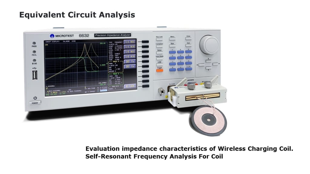
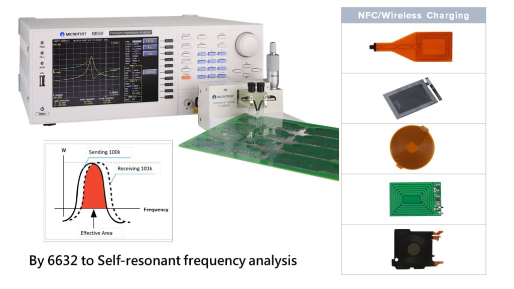
Evaluation impedance characteristics of RFID / NFC / automotive wireless of antennas
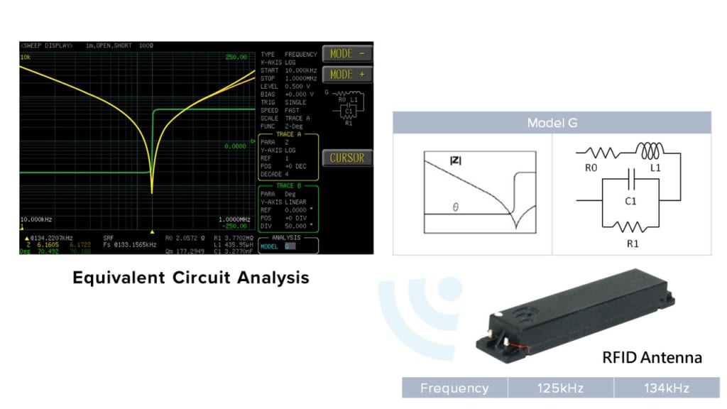
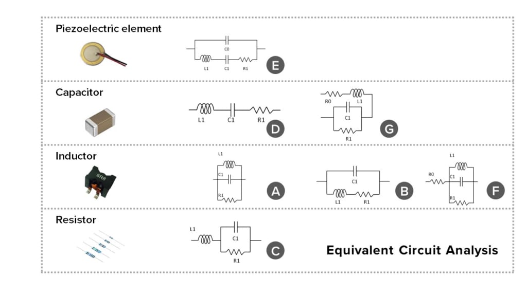
Equivalent Circuit Analysis (Option)
It has seven different models, combine with different types of parameters ( R, L, C) help customers model the impedance versus frequency characteristics and self-resonant frequency (SRF).
Four Parameters Displayed Simultaneously
7.0”TFT, 800×480 color screen, and four parameters can displayed simultaneously.
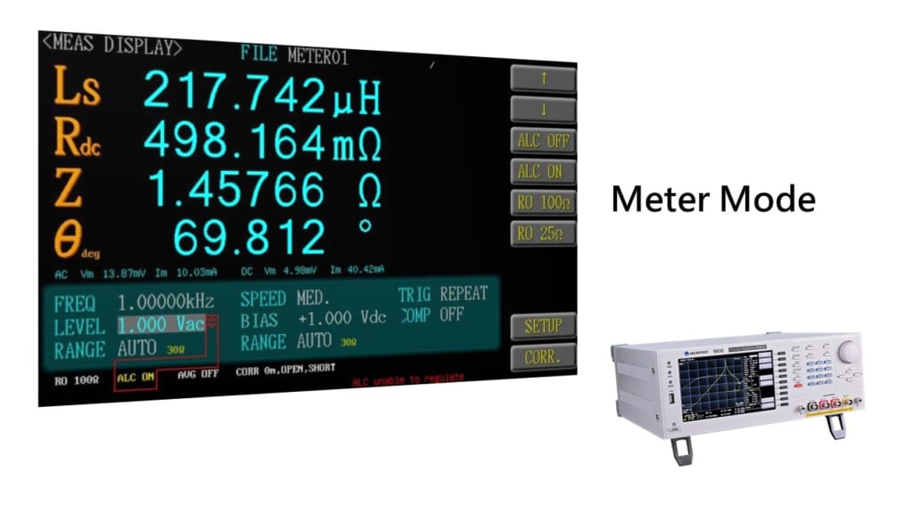
Measure Inductor (DCR)
Inductor coil turns and winding materials will affect DCR value. The key parameters for inductor are Ls / Lp / Q / SRF / DCR.
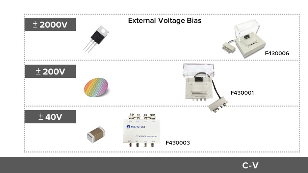
Evaluation of DC bias voltage characteristics with semiconductor wafer or ceramic multilayer capacitors.
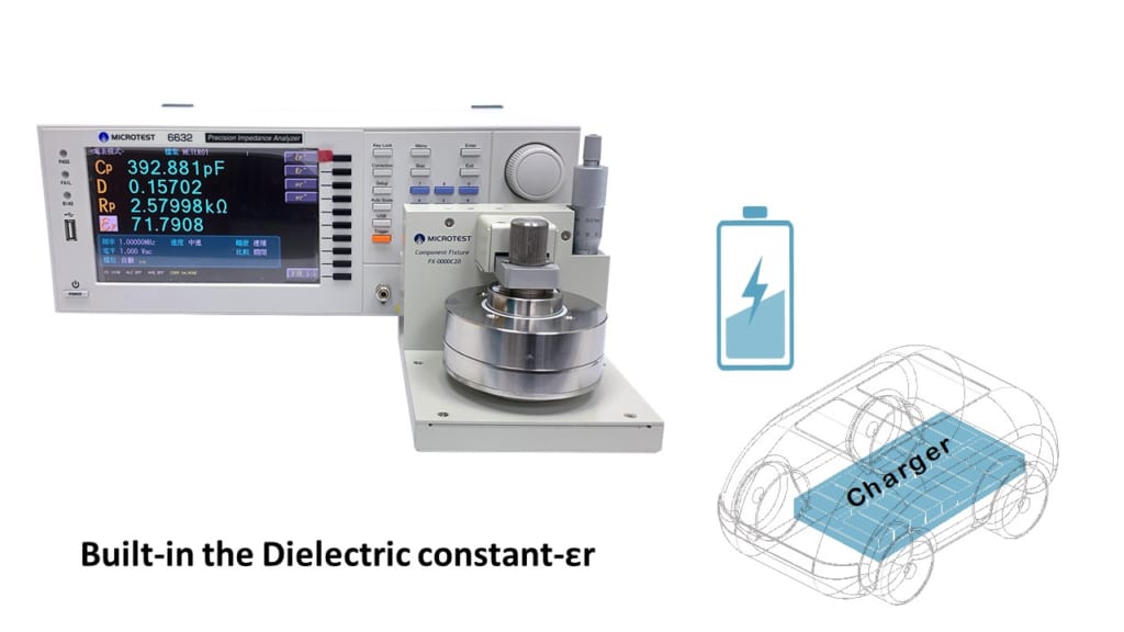
- Built-in the Dielectric constant-εr
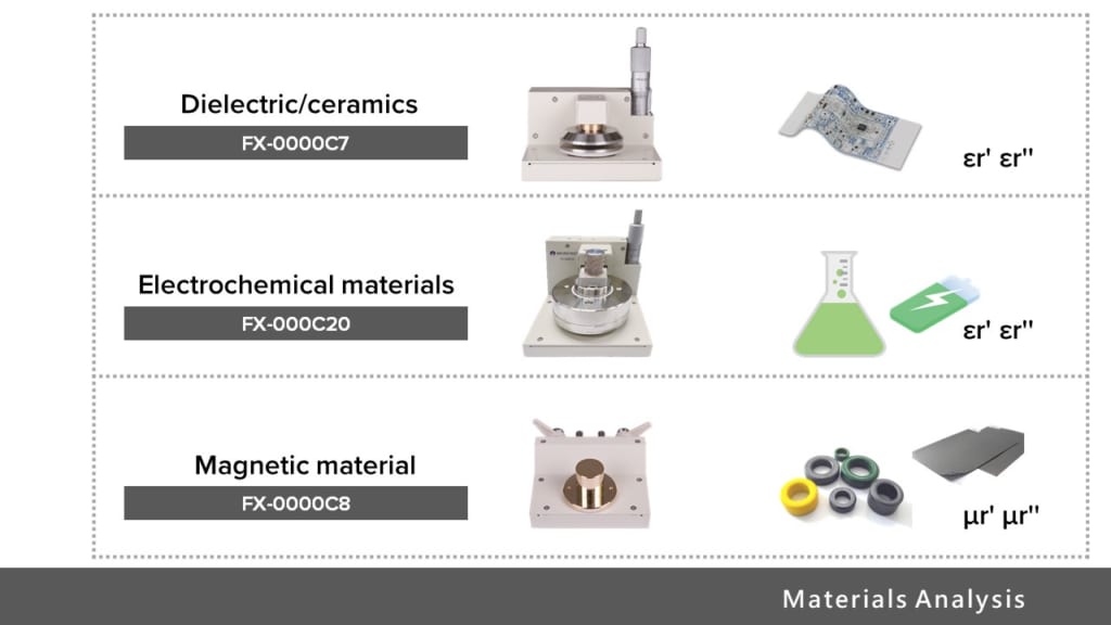
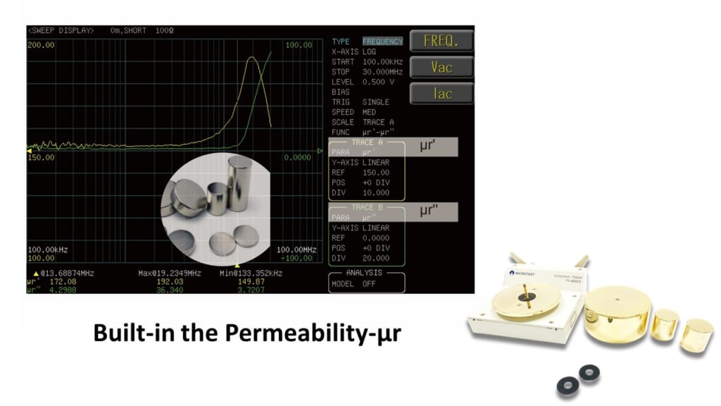
- Built-in the Permeability-μr
Features
- Frequency range: DC, 10Hz to 1/3/5/10/20/30MHz/50MHz
- Basic accuracy up to ±0.08% (typical ±0.05% )
- Automatic Level Control (ALC)
- Output impedance 25Ω/100Ω, switchable
- Support meter mode and list mode, sweep mode
- Equivalent Circuit Analysis
- Built-in DC Bias voltage ±12V
- Ultra-high measuring speed < 3ms
- Open circuit/short circuit/load correction function
- Comparator function
- BIN classification function
- Built-in the Permeability-μr
- Built-in the Dielectric constant-εr
Application
The induction coil for wireless charging in a mobile phone. Due to the manufacturing process, the wiring density layout from the induction coil will affect the original capacitance. The size of the parallel equivalent capacitance in the coil is the key to determine whether the product can be successful in high frequency application. It can affect the receiving function/wireless charging of an antenna. With this element analysis, we can accurately determine the RLC value to ensure the quality of the induction coil.
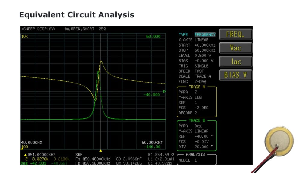
Model E is suitable for measuring and analyzing the resonators, piezoelectric element or transducer. The two-resonance frequency characteristic diagram presented above is suited for Model E.
Testing PC board inductance coil.
Utilizing the 6632 Impedance Analyzer to Measure Component Impedance Characteristics
Functions and Specifications
| Model | 6632 |
| Frequency Range | 10Hz-50MHz (6632-50)
10Hz-30MHz (6632-30) 10Hz-20MHz (6632-20) 10Hz-10MHz (6632-10) 10Hz-5MHz (6632-5) 10Hz-3MHz (6632-3) 10Hz-1MHz (6632-1) |
| Frequency Setting | Continuity |
| Frequency Resolution | ±0.01% |
| Frequency Output Accuracy | 100mHz, 6-bit Frequency Input |
| Basic Accuracy | typical ±0.05% |
| AC Drive Level | Test Signal Voltage Level
10mV – 2Vrms(100Ω) 10mV – 1Vrms(25Ω) |
| Voltage Minimum Resolution
1mV |
|
| Accuracy
ALC ON:6% * Voltage ±2mV ALC OFF:10% * Voltage ±2mV |
|
| Test Signal Current Level
200µA – 20mArms |
|
| Current Minimum Resolution
10µA |
|
| Accuracy
ALC ON:6% * Current ± 20µA ALC OFF:10% * Current ± 20µA |
|
| DC Drive Level | 1V (fixed) |
| Output Impedance | 25Ω/100Ω (switchable) |
| Measurement Mode | Meter mode, list mode |
| Measurement Parameters | |Z|、|Y|、θ、X、R、G、B、L、D、Q、DCR、C、ε and μr |
| Test Time (Fastest) | < 3mS |
| Parameters | Range |
| |Z| | 0.000 mΩ to 9999.99 MΩ |
| R, X | ± 0.000 mΩ to 9999.99 MΩ |
| |Y| | 0.00000 μS to 999.999 kS |
| G, B | ± 0.00000 μS to 999.999 kS |
| θRAD | ± 0.00000 to 3.14159 |
| θDEG | ± 0.000° to 180.000° |
| Cs, Cp | ± 0.00000 pF to 9999.99 F |
| Ls, Lp | ± 0.00 nH to 9999.99 kH |
| D | 0.00000 to 9999.99 |
| Q | 0.00 to 9999.99 |
| Δ | ± 0.00% to 9999.99% |
| Rdc | 0.00 mΩ to 99.9999 MΩ |
| εr’ εr” | 0 to 100000 |
| μr’ μr” | 0 to 100000 |
| Measurement Circuit | Series/Parallel |
| Correction | Open Circuit/Short Circuit/Load correction |
| Cable Compensation | 0 / 0.5 / 1 /2 (m) |
| BIN | ABS、ΔABS、Δ%、OFF |
| Comparator | 9 |
| List Mode | 50 groups of Multi-steps setting (Each group contains up to 15 steps) |
| Bulit-in Storge | 100 sets LCR setting documents, 50 groups of list mode setting |
| USB Host Storge | LCR setting documents, list mode setting document, BMP graphics, Sweep screen and test result data |
| Trigger Test | Auto, manual, RS-232, GPIB, Handler |
| Power Supply | Voltage:90-264Vac |
| Frequency:47-63Hz | |
| Power consumption | 30VA |
| Environment | Temperature:10℃-40℃ |
| Humidity:20-90%RH | |
| Dimension | 336x147x340 mm (W*H*D) |
| Weight | 3 Kg |
| Interface | RS-232、Handler、LAN、USB Host、USB Device |
| Display | Color Screen, 7″ TFT (800*480) |
![]()
To view the pdf files, the Adobe Reader from Adobe Systems is required.