




This website uses cookies so that we can provide you with the best user experience possible. Cookie information is stored in your browser and performs functions such as recognising you when you return to our website and helping our team to understand which sections of the website you find most interesting and useful.


ITEMLIST
Products Infomation

- Products by Category
- Electronic Measuring Instruments
- Power Supplies / Electronic Load Devices
- Multifunctional Electronic Load PLZ-5W Series
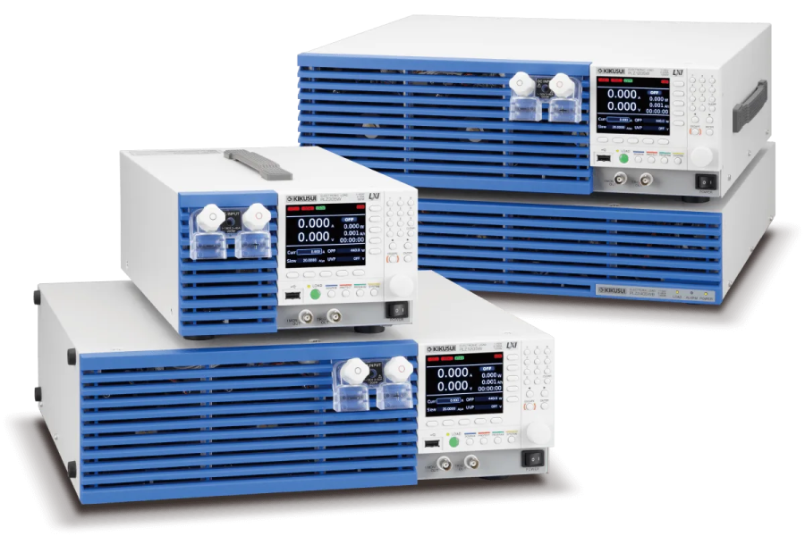
High-speed response, universal interface, large-scale system compatibility
The PLZ-5W series electronic load is the successor of the highly respected PLZ-4W that continues the series tradition of high
specification and excellent build quality.
New improvements include a user-friendly LCD color display and a wide voltage range from 0.25 V to 150 V. Custom voltage/current profiles can now be programmed using the new ARB function, ideal for LED driver and solar panel testing. The PLZ-5W now includes 6 basic modes of operation (CC, CR, CV, CP, CC+CV, & CR+CV) for optimal flexibility in any test facility.
The PLZ-5W is now equipped with a high-speed response feature boasting a maximum slew rate of 60 A/us (PLZ1205W) and a minimum setting resolution of 10 uA (PLZ205W).
Additional features include a soft-start function, variable slew rate, selectable response mode (CV/CR mode), switching function, ABC programmable memory, 20 user-defined setup configurations, and a sequence function. The high-speed response of the PLZ-5W is ideal for the development and testing of modern day power supplies that require sudden changes in current at high speeds as well as for testing of current clamps and transducers. The PLZ-5W series is available in 4 standard models which can be incrementally expanded by adding booster units (PLZ2405W) for a maximum of 10.8 kW/2160 A. The PLZ-5W now is equipped with a diverse digital communication interface supporting LAN (LXI), USB, RS232C, analog control, and GPIB as a factory option.
Multifunctional Electronic Load
Model:
PLZ-5W Series
Maker:
KIKUSUI ELECTRONICS CORPORATION
Features
- Operation voltage: 0.25 V to 150 V
- High speed slew rate: 60 A/μs
- Arbitrary I-V characteristics: Installed “ARB mode”
- Parallel operation feature: The total current and power capacities can be increased to the maximum of 10.8 kW (2160 A) by connecting the booster units.
- New high visibility color display.
- Improved sequence feature (Maximum 10000 steps)
- LAN (LXI Compliant)/USB/RS232C standard interface *GPIB optional
- Setup memory can be saved to or loaded from a USB flash drive.
Line up
| SKU | Rated operating voltage [V] | Rating current [A] | Rating Power [W] |
|---|---|---|---|
| PLZ205W | 0.25 to 150 | 40 | 200 |
| PLZ405W | 80 | 400 | |
| PLZ1205W | 240 | 1200 |
Specifications
Rating
| Model | PLZ205W | PLZ405W | PLZ1205W |
|---|---|---|---|
| Operating voltage | 0.25 V to 150 V *1 | ||
| Current *2 | 40 A | 80 A | 240 A *3 |
| Power | 200W | 400W | 1200W |
| The minimum operating voltage | approximately 0.05 V. (At the load input terminals on the rear panel.) | ||
| Input resistance when the load is off | Approx. 660 kΩ *4 | ||
| Load input terminal’s isolation voltage | ±500 V | ||
*1 In switching mode, for every slew rate setting of 1 A/μs, the minimum operating voltage (including the voltage drop due to the wiring inductance component) increases by approx. 150 mV for the PLZ205W, approx. 125 mV for the PLZ405W, and approx. 75 mV for the PLZ1205W.
*2 If the input voltage is 1 V or less, the current is reduced by 10% per 0.1 V.
*3 80 A for the load input terminals on the front panel. The specifications of the PLZ-5W are for the load input terminals on the rear panel and the load input terminals on the front panel may not meet the specifications.
*4 In the case of parallel operation using the same models, approx. 660/number of units kΩ.
Constant current (CC) mode
| Model | PLZ205W | PLZ405W | PLZ1205W | ||
|---|---|---|---|---|---|
| Operating range | Range H | 0 A to 40 A | 0 A to 80 A | 0 A to 240 A | |
| Range M | 0 A to 4 A | 0 A to 8 A | 0 A to 24 A | ||
| Range L | 0 A to 0.4 A | 0 A to 0.8 A | 0 A to 2.4 A | ||
| Setting range | Range H | 0 A to 42 A | 0 A to 84 A | 0 A to 252 A | |
| Range M | 0 A to 4.2 A | 0 A to 8.4 A | 0 A to 25.2 A | ||
| Range L | 0 A to 0.42 A | 0 A to 0.84 A | 0 A to 2.52 A | ||
| Resolution | Range H | 1 mA | 2 mA | 5 mA | |
| Range M | 0.1 mA | 0.2 mA | 0.5 mA | ||
| Range L | 0.01 mA | 0.02 mA | 0.05 mA | ||
| Setting accuracy | Range H | ±(0.2% of set + 0.1% of range) | |||
| Range M | ±(0.2% of set + 0.3% of range) | ||||
| Range L | ±(0.2% of set + 1% of range) | ||||
| Parallel operation | Range H | ±(0.4% of set + 0.8% of range) | |||
| Range M | ±(0.4% of set + 0.8% of range) | ||||
| Range L | ±(0.4% of set + 5% of range) | ||||
| Input line regulation *1 | 4 mA | 8 mA | 24 mA | ||
| Ripple | rms *2 | 4 mA | 8 mA | 24 mA | |
| p-p *3 | 40 mA | 80 mA | 200 mA | ||
*1 When the input voltage is changed from 1 V to 150 V at a current of rated power / 150 V.
*2 Measurement frequency bandwidth: 10 Hz to 1 MHz
*3 Measurement frequency bandwidth: 10 Hz to 20 MHz
Constant resistance (CR) mode
| Model | PLZ205W | PLZ405W | PLZ1205W | ||
|---|---|---|---|---|---|
| Operating range *1 | Range H | 40 S to 0.002 S (0.025 Ω to 500 Ω) | 80 S to 0.004 S (0.0125 Ω to 250 Ω) | 240 S to 0.012 S (0.0042 Ω to 83.333 Ω) | |
| Range M | 4 S to 0.0002 S (0.25 Ω to 5000 Ω) | 8 S to 0.0004 S (0.125 Ω to 2500 Ω) | 24 S to 0.0012 S (0.042 Ω to 833.33 Ω) | ||
| Range L | 400 mS to 0.02 mS (2.5 Ω to 50000 Ω) | 800 mS to 0.04 mS (1.25 Ω to 25000 Ω) | 2400 mS to 0.12 mS (0.42 Ω to 8333.3 Ω) | ||
| Setting range | Range H | 42 S to 0 S (0.0238 Ω to Open) | 84 S to 0 S (0.0119 Ω to Open) | 252 S to 0 S (0.00397 Ω to Open) | |
| Range M | 4.2 S to 0 S (0.238 Ω to Open) | 8.4 S to 0 S (0.119 Ω to Open) | 25.2 S to 0 S (0.0397 Ω to Open) | ||
| Range L | 420 mS to 0 S (2.38 Ω to Open) | 840 mS to 0 S (1.19 Ω to Open) | 2520 mS to 0 S (0.397 Ω to Open) | ||
| Resolution | Range H | 1 mS | 2 mS | 5 mS | |
| Range M | 0.1 mS | 0.2 mS | 0.5 mS | ||
| Range L | 0.01 mS | 0.02 mS | 0.05 mS | ||
| Setting accuracy *2 | Range H | ±(0.5% of set + 0.5% of range) | |||
| Range M | ±(0.5% of set + 0.5% of range) | ||||
| Range L | ±(0.5% of set + 1.5% of range) | ||||
| Parallel operation | Range H | ±(0.5% of set + 1.5% of range) | |||
| Range M | ±(0.5% of set + 1.5% of range) | ||||
| Range L | ±(0.5% of set + 5% of range) | ||||
*1 Conductance [S] = input current [A]/input voltage [V] = 1 / resistance [Ω]
*2 Converted value at the input current. At the sensing terminals during remote sensing.
Constant voltage (CV) mode
| Model | PLZ205W | PLZ405W | PLZ1205W | |
|---|---|---|---|---|
| Operating range | Range H | 0.25 V to 150 V | ||
| Range L | 0.25 V to 15 V | |||
| Setting range | Range H | 0 V to 157.5 V | ||
| Range L | 0 V to 15.75 V | |||
| Resolution | Range H | 5 mV | ||
| Range L | 0.5 mV | |||
| Setting accuracy *1 | ±(0.1% of set + 0.1% of range) | |||
| Parallel operation | ±(0.2% of set + 0.2% of range) | |||
| Input voltage variation*2 | 12 mV | |||
*1 With the input voltage within the operating range, and at the sensing terminals during remote sensing.
*2 For a current change in the range of 10% to 100% of the rating at an input voltage of 5 V (during remote sensing).
Constant power (CP) mode
| Model | PLZ205W | PLZ405W | PLZ1205W | ||
|---|---|---|---|---|---|
| Operating range | Range H | 20 W to 200 W | 40 W to 400 W | 120 W to 1200 W | |
| Range M | 2 W to 20 W | 4 W to 40 W | 12 W to 120 W | ||
| Range L | 0.2 W to 2 W | 0.4 W to 4 W | 1.2 W to 12 W | ||
| Setting range | Range H | 0 W to 210 W | 0 W to 420 W | 0 W to 1260 W | |
| Range M | 0 W to 21 W | 0 W to 42 W | 0 W to 126 W | ||
| Range L | 0 W to 2.1 W | 0 W to 4.2 W | 0 W to 12.6 W | ||
| Resolution | Range H | 0.005 W | 0.01 W | 0.05 W | |
| Range M | 0.0005 W | 0.001 W | 0.005 W | ||
| Range L | 0.00005 W | 0.0001 W | 0.0005 W | ||
| Setting accuracy | Range H | ±(0.5% of range + 0.04A×Vin *1) | ±(0.5% of range + 0.08A×Vin *1) | ±(0.5% of range + 0.24A×Vin *1) | |
| Range M | ±(0.5% of range + 0.008A×Vin *1) | ±(0.5% of range + 0.016A×Vin *1) | ±(0.5% of range + 0.048A×Vin *1) | ||
| Range L | ±(1% of range + 0.004A×Vin *1) | ±(1% of range + 0.008A×Vin *1) | ±(1% of range + 0.024A×Vin *1) | ||
| Parallel operation | Range H | ±(2% of range + 0.4% current range ×Vin *1) | |||
| Range M | ±(2% of range + 0.4% current range ×Vin *1) | ||||
| Range L | ±(2% of range + 2.5% current range ×Vin *1) | ||||
*1 Vin: Rear panel load input terminal voltage or sensing terminal voltage.
General Specifications
| Model | PLZ205W | PLZ405W | PLZ1205W | |
|---|---|---|---|---|
| Input voltage range/ Input frequency range | 100 Vac to 240 Vac (90 Vac to 250 Vac) single phase, continuous / 47 Hz to 63 Hz | |||
| Power consumption | 50VAmax | 50VAmax | 85VAmax | |
| Inrush current | 45A Peak | |||
| Environmental conditions | Operating temperature range / Operating humidity range | 0 °C to 40 °C (32 °F to 104°F) / 20%rh to 85%rh (no condensation) | ||
| Storage temperature range / Storage humidity range | -20 °C to 70 °C (-4 °F to 158°F) / 90%rh or less (no condensation) | |||
| Installation location | Indoor use, altitude of up to 2000 m, overvoltage category II. | |||
| Insulation resistance | Between primary and input terminals | 500Vdc, 30 MΩ or more (70%rh or less) | ||
| Between primary and chassis | ||||
| Between input terminals and chassis | ||||
| Withstanding voltage | Between primary and input terminals | No abnormalities at 1500 Vac for 1 minute. | ||
| Between primary and chassis | No abnormalities at 1500 Vac for 1 minute. | |||
| Between input terminals and chassis | No abnormalities at 750 Vac for 1 minute. | |||
| Dimensions Unit: mm (inches) | 214.5 (8.45)W×124 (4.88)H×400 (15.75)Dmm(inches) | 429.5 (16.91)W×128 (5.04)H×400 (15.75)Dmm(inches) | ||
| Weight | Approx. 7 kg (15.4 lb.) | Approx. 7.5 kg (16.5 lb.) | Approx. 14 kg (30.9 lbs) | |
| Accessories | Power cord, Rear-panel load input terminal cover, Load input terminal screw set (2 sets), Screws for the rear-panel load input terminal cover (2 pcs.), Front-panel load input terminal cover, Front-panel load input knob set, External control connector kit, Setup Guide, CD-ROM, Quick Reference, Safety Information | |||
| Electromagnetic compatibility (EMC) *1, *2 | Complies with the requirements of the following directive and standards. EMC Directive 2014/30/EU, EN 61326-1 (Class A*3), EN 55011 (Class A*3, Group 1*4), EN 61000-3-2, EN 61000-3-3 Applicable under the following conditions.The maximum length of all cabling and wiring connected to the PLZ-5W must be less than 3 m. |
|||
| Safety *1 | Complies with the requirements of the following directive and standards. Low Voltage Directive 2014/35/EU *2 EN 61010-1 (Class I *5, Pollution Degree 2 *6) | |||
*1 Does not apply to specially ordered or modified PLZ-5Ws.
*2 Only for models with have CE mark/UKCA mark on their body.
*3 This is a Class A equipment. This product is intended for use in an industrial environment. This product may cause interference if used in residential areas. Such use must be avoided unless the user takes special measures to reduce electromag-netic emissions to prevent interference to the reception of radio and television broadcasts.
*4 This is a Group 1 equipment. This product does not generate and/or use intentionally radio-frequency energy, in the form of electromagnetic radiation, inductive and/or capacitive coupling, for the treatment of material or inspection/analysis purpose.
*5 This is a Class I equipment. Be sure to ground this product’s protective conductor terminal. The safety of this product is only guaranteed when the product is properly grounded.
*6 Pollution is addition of foreign matter (solid, liquid or gaseous) that may produce a reduction of dielectric strength or surface resistivity. Pollution Degree 2 assumes that only non-conductive pollution will occur except for an occasional temporary con-ductivity caused by condensation.

To view the pdf files, the Adobe Reader from Adobe Systems is required.