




This website uses cookies so that we can provide you with the best user experience possible. Cookie information is stored in your browser and performs functions such as recognising you when you return to our website and helping our team to understand which sections of the website you find most interesting and useful.


ITEMLIST
Products Infomation

- Products by Category
- Electronic Measuring Instruments
- Power Supplies / Electronic Load Devices
- KIKUSUI Slim Wide Range Variable Switching Power Supply PWX Series
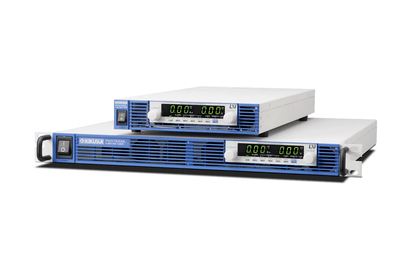
Ideal for N-to-M network-based remote control and monitoring. A Next-Generation Rack-Mounted Power Supply
The PWX Series is a next-gen, rack-mounted DC power supply, designed for optimal remote control and monitoring via networked systems. It features USB, RS232C, and LXI-compliant LAN interfaces for seamless browser-based access on multiple devices. With power outputs of 750 W and 1500 W, and a universal voltage range, it includes PFC circuits, multi-channel support, and safety functions, ensuring versatile, efficient network integration.
Slim Wide Range Variable Switching Power Supply
Model:
PWX Series
Maker:
KIKUSUI ELECTRONICS CORPORATION
Features
The PWX series is a CV/CC programmable regulated DC power supply optimally designed for rack-mounted operation. To increase its mounting efficiency, it has a 19-inch rack width with a thin shape and intakes and outtakes for cooling on only the front and back surfaces so that it can be mounted flush top and bottom.
Furthermore, this series is equipped with essential communication interfaces for system upgrades, including LAN, USB, and RS232C as standard. By utilizing the VMCB (Virtual Multichannel Bus) function*, efficient remote control and monitoring of 1-to-N, N-to-M, and large-scale network types can be achieved. LAN communication allows control and monitoring from web browsers on PCs, smartphones, and tablets. Additionally, it is certified for LXI (LAN eXtensions for Instrumentation), making it easy to configure when connecting to measurement systems via LAN. Remote management of power supplies located in separate buildings can also be easily realized.
The output specifications include two types of output power: 750W and 1500W, with a wide range of voltage and current settings possible in a “3:1” power type. For example, the PWX1500ML with a rated output power of 1500W allows seamless operation from 80V-18.75A to 26.8V-56A. The input power voltage is also a universal specification of 85V to 265V, with a built-in PFC (Power Factor Correction) circuit to suppress harmonic current. Other features include analog external control and monitor output, master-slave parallel operation function, various protection functions, memory functions, etc.
*Supported from Half-Rack Model Ver2.0
Equipment
Equipped with standard LAN interface and VMCB (Virtual Multi-Channel Bus) function
to support network-based remote control and monitoring
The PWX series is equipped with LAN, USB, and RS232C interfacesas standard features. By using the feature of virtual multi-channelbus (VMCB)*1, it allows you to control remotely and monitoringfor 1-to-N as well as N-to-M for large-scale networks.
In particular,the LAN interface is LXI compliant, enabling you to easily controland monitor the power supply through a browser on a PC, smartphone,or tablet by accessing the web server built into the PWXseries.
Additionally, the optional application software, Wavy forPWX (SD013-PWX), sequence creation and control software,allows you to change settings for specific channels (in individual)on VMCB-connected PWX series power supplies, and lets youperform batch control using global commands*2. You can alsoturn the output ON and OFF on multiple units and adjust theoutput voltage and current.
*1: This function for the PWX750ML applies to the firmware version 2.0 and later.
*2: This is only enabled for “Direct control” on Wavy for PWX. Global commands that can be also used under control with VXI-11, HiSLIP, and SCPI-RAW.
Specifications
| Model Type | Rated voltage range | Example of Output rating voltage | 750W | 1500W | ||
| L (LF) | 10V to 30V | 10V | 75A to 25A | 75A | 150A to 50A | 150A |
| 12.5V | 60A | 120A | ||||
| 15V | 50A | 100A | ||||
| 20V | 37.5A | 75A | ||||
| 30V | 25A | 50A | ||||
| ML (MLF) | 26.8V to 80V | 26.8V | 28A to 9.37A | 28A | 56A to 18.75A | 56A |
| 30V | 25A | 50A | ||||
| 35V | 21.4A | 42.8A | ||||
| 40V | 18.75A | 37.5A | ||||
| 45V | 16.66A | 33.33A | ||||
| 60V | 12.5A | 25A | ||||
| 80V | 9.375A | 18.75A | ||||
| MH (MHF) | 75V to 230V | 75V | 10A to 3.26A | 10A | 20A to 6.52A | 20A |
| 80V | 9.375A | 18.75A | ||||
| 100V | 7.5A | 15A | ||||
| 150V | 5A | 10A | ||||
| 200V | 3.75A | 7.5A | ||||
| 230V | 3.26A | 6.52A | ||||
| H (HF) | 214.2V to 650V | 214.2V | 3.5A to 1.153A | 3.5A | 7A to 2.307A | 7A |
| 300V | 2.5A | 5A | ||||
| 400V | 1.875A | 3.75A | ||||
| 500V | 1.5A | three a (baseball) | ||||
| 600V | 1.25A | 2.5A | ||||
| 650V | 1.153A | 2.307A | ||||
PWX Series 750W model
AC input
| Item/Model | PWX750LF | PWX750MLF | PWX750MHF | PWX750HF | |
|---|---|---|---|---|---|
| Half rack size | PWX750ML | ||||
| Nominal input rating | 100 Vac to 240 Vac, 50 Hz to 60 Hz, single phase | ||||
| Input voltage range | 85 Vac to 265 Vac | ||||
| Input frequency range | 47 Hz to 63 Hz | ||||
| Current (MAX) *1 | 100 Vac | 10.5A | |||
| 200 Vac | 5.25A | ||||
| Inrush current *2 | 70 A or less | ||||
| Power (MAX) *3 | 1100VA | ||||
| Power factor (TYP) *1 | 0.99 (input voltage 100 V), 0.97 (input voltage 200 V) | 0.98 (input voltage 100 V), 0.96 (input voltage 200 V) | |||
| Efficiency *1 | 74 % or greater | ||||
| Hold-up time for power interruption *3 | 20 ms or greater | ||||
*1. With rated load.
*2. Excludes the charge current component that flows through the capacitor of the internal EMC filter circuit immediately after the POWER switch is turned on (for approximately 1 ms).
*3. 100 Vac with rated load.
Output
| Item/Model | PWX750LF | PWX750MLF | PWX750MHF | PWX750HF | ||
|---|---|---|---|---|---|---|
| Half rack size | PWX750ML | |||||
| Rating | Output voltage *1 | 30V | 80V | 230V | 650V | |
| Output current *1 | 75A | 28A | 10A | 3.5A | ||
| Output power | 750W | |||||
| Voltage | Setting range | 0V to 31.5V | 0V to 84V | 0V to 241.5V | 0V to 682.5V | |
| Setting accuracy | ±(0.05%of set+0.05% of rtg) | |||||
| Line regulation *2 | ±5mV | ±10mV | ±25mV | ±67mV | ||
| Load regulation *3 | ±5mV | ±10mV | ±25mV | ±67mV | ||
| Transient response *4 | 1 ms or less | 7 ms or less | ||||
| Ripple noise *5 | (p-p)*6 | 60mV | 80mV | 120mV | 330mV | |
| (rms) *7 | 8mV | 8mV | 25mV | 60mV | ||
| Rise time | Rated load | 100ms | ||||
| No load | 100ms | |||||
| Fall time *8 | Rated load | 100ms | 150ms | 250ms | ||
| No load | 450ms | 550ms | 1500ms | 3000ms | ||
| Maximum remote sensing compensation voltage (single line) | 1.5V | 4V | 5V | 5V | ||
| Temperature coefficient (MAX) *9 | 100 ppm/°C (during external control) | |||||
| Current | Setting range | 0A to 78.75A | 0A to 29.4A | 0A to 10.5A | 0A to 3.675A | |
| Setting accuracy *10 | ±(0.5%of set+0.1% of rtg) | |||||
| Line regulation | ±9.5mA | ±4.8mA | ±3mA | ±2.35mA | ||
| Load regulation | ±20mA | ±10.6mA | ±7mA | ±5.7mA | ||
| Ripple noise *11 | (rms) *7 | 150mA | 65mA | 30mA | 15mA | |
| Temperature coefficient (TYP) *9 | 100 ppm/°C | |||||
*1. The maximum output voltage and current are limited by the maximum output power.
*2. 85 Vac to 135 Vac or 170 Vac to 265 Vac, fixed load.
*3. The amount of change that occurs when the load is changed from no load to rated load (rated output power/rated output voltage) with rated output voltage. The value is measured at the sensing point.
*4. The amount of time required for the output voltage to return to a value within “rated output voltage ± (0.1 % + 10 mV).” The load current fluctuation is 50 % to 100 % of the maximum current with the set output voltage.
*5. Measured using an RC-9131 1:1 probe that conforms to the JEITA specifications. At the rated output current.
*6. When the measurement frequency bandwidth is 10 Hz to 20 MHz.
*7. When the measurement frequency bandwidth is 5 Hz to 1 MHz.
*8.When the breeder circuit on/off setting is on.
*9. When the ambient temperature is within 0 °C and 50 °C.
*10. When the output voltage (Rated Power ÷ Rated Current) is 10 % to 100 % of the rating. At the rated output current.
Display function
| Item/Model | PWX750LF | PWX750MLF | PWX750MHF | PWX750HF | |
|---|---|---|---|---|---|
| Half rack size | PWX750ML | ||||
| Voltage display | Maximum display | 99.99 (fixed decimal point) | 999.9 (fixed decimal point) | ||
| Display accuracy | ±(0.2 % of rdng +5 digits) | ||||
| Current display | Maximum display | 99.99 (fixed decimal point) | 9.999 (fixed decimal point) | ||
| Display accuracy | ±(0.5 % of rdng +5 digits) | ||||
| Power display *1 | The PWR DSPL LED lights in red. | ||||
| Maximum display | 9999 | ||||
| Display accuracy | Displays the result of multiplying the current and voltage | ||||
| Operation display | OUTPUT ON/OFF, CV operation, CC operation,Alarm operation, Remote operation (LAN operation),Key lock operation, Preset memory | ||||
*1. Press PWR DSPL to display the power on the ammeter. Each time you press this key, the display switches between power and current.
General
| Item/Model | PWX750LF | PWX750MLF | PWX750MHF | PWX750HF | |
|---|---|---|---|---|---|
| Half rack size | PWX750ML | ||||
| Environmental conditions | Operating environment | Indoor use, overvoltage category II | |||
| Operating temperature/ humidity | 0 °C to +50 °C (32 °F to +122 °F)/ 20 %rh to 85 %rh (no condensation) | ||||
| Storage temperature/ humidity | -10 °C to +60 °C (14 °F to +140 °F)/ 90 %rh or less (no condensation) | ||||
| Altitude | Up to 2000 m | ||||
| Cooling method | Forced air cooling using fan | ||||
| Grounding polarity | Negative grounding or positive grounding possible | ||||
| Isolation voltage | ± 250 Vmax | ± 500 Vmax | ± 800 Vmax | ||
| Isolated analog interface *1 | ± 60 Vmax | ||||
| Withstanding voltage | Between input and FG | No abnormalities when 1500 Vac is applied for 1 minute | |||
| Between input and output | No abnormalities at 2000 Vac for 1 minute | No abnormalities at 2250 Vac for 1 minute | |||
| Between output and FG | No abnormalities at 1500 Vdc for 1 minute | No abnormalities at 1600 Vac for 1 minute | No abnormalities at 2000 Vdc for 1 minute | ||
| Between input and Isolated Analog Interface *1 | No abnormalities at 2650 Vac for 1 minute | ||||
| Between output and Isolated Analog Interface *1 | No abnormalities at 2300 Vdc for 1 minute | No abnormalities at 2650 Vac for 1 minute | No abnormalities at 3300 Vac for 1 minute | ||
| Insulation resistance | 500 Vdc, 100 MΩ or more (70 % or less) | 1000 Vdc, 100 MΩ or more (70 % or less) | |||
| Between output and FG | 500 Vdc, 40 MΩ or more(70 % or less) | 1000 Vdc, 40 MΩ or more (70 % or less) | |||
| Safety | Conforms to the requirements of the directive and standard below. Low Voltage Directive 2014/35/EU *3 EN 61010-1 (Class I *4、Pollution degree 2 *7) |
||||
| Electromagnetic compatibility (EMC) *2*3 | Conforms to the requirements of the directive and standard below. EMC Directive 2014/30/EU EN 61326-1 (Class A *5) EN 55011 (Class A *5、Group 1 *6) EN 61000-3-2、EN 61000-3-3 Applicable under the following conditions The maximum length of all cabling and wiring connected to the PWX series must be less than 3 m. |
||||
| Dimensions (maximum)/Weight | 422.8(485) W×43(44) H×500(580) Dmm/Approx. 8 kg | 422.8(485) W×43(44) H×500(580) Dmm/Approx. 7.5 kg | |||
| Half rack size | 214 W×43(55) H×437(490) Dmm/Approx. 5 kg | ||||
| Accessories | AC cable : 1 wire, Output terminal cover: 1 pc., Output terminal M8 bolt set: M8 bolts ×2 sets(Bolt, nut, spring washer, and washer for each bolt) *PWX750ML includes M6 bolt set, Chassis connection wire: 1 wire, J1 connector plug kit: 1 set (Housing: 1 pc., Connector: 1 pc., Plug: 1 pc., Strain relief: 1 pc., Clips: 2 pcs., and two types of Screws: 2 pcs.,), Packing list: 1 copy, Quick reference (1 each for English and Japanese), Safety precautions: 1 copy, China RoHS sheet: 1 copy, CD-ROM: 1 disc | ||||
*1 Factory option.
*2 Does not apply to specially ordered or modified PWXs.
*3 Limited to products that have the CE/UKCA marking on their panels. Not be in compliance with EMC limits unless the ferrite core is attached on the cable for connection of J1 connector.
*4 This is a Class A equipment. The PWX is intended for use in an industrial environment. This product may cause interference if used in residential areas. Such use must be avoided unless the user takes special measures to reduce electromagnetic emissions to prevent interference to the reception of radio and television broadcasts.
*5 This is a Group 1 equipment. The PWX does not generate and/or use intentionally radio-frequency energy, in the from of electromagnetic radiation, inductive and/or capacitive coupling, for the treatment of material or inspection/analysis purpose.
*6 This is a Class I equipment. Be sure to ground the PWX’s protective conductor terminal. The safety of this product is only guaranteed when the product is properly grounded.
*7 Pollution is addition of foreign matter (solid, liquid or gaseous) that may produce a reduction of dielectric strength or surface resistivity. Pollution Degree 2 assumes that only non-conductive pollution will occur except for an occasional temporary conductivity caused by condensation.
PWX Series 150W model
AC input
| Item/Model | PWX1500L | PWX1500ML | PWX1500MH | PWX1500H | |
|---|---|---|---|---|---|
| Nominal input rating | 100 Vac to 240 Vac, 50 Hz to 60 Hz, single phase | ||||
| Input voltage range | 85 Vac to 265 Vac | ||||
| Allowable frequency range | 47 Hz to 63 Hz | ||||
| Current (MAX) *1 | 100 Vac | 21 A | |||
| 200 Vac | 10.5 A | ||||
| Inrush current *2 | 70 A or less | ||||
| Power (MAX) *3 | 2200 VA | ||||
| Power factor (TYP) *1 | 0.99 (input voltage 100 V), 0.97 (input voltage 200 V) | 0.98 (input voltage 100 V), 0.96 (input voltage 200 V) | |||
| Efficiency *1 | 74 % or greater | ||||
| Hold-up time for power interruption *3 | 20 ms or greater | ||||
*1. With rated load.
*2. Excludes the charge current component that flows through the capacitor of the internal EMC filter circuit immediately after the POWER switch is turned on (for approximately 1 ms).
*3. 100 Vac with rated load.
Output
| Item/Model | PWX1500L | PWX1500ML | PWX1500MH | PWX1500H | ||
|---|---|---|---|---|---|---|
| Rating | Output voltage *1 | 30 V | 80 V | 230 V | 650 V | |
| Output current *1 | 150 A | 56 A | 20 A | 7 A | ||
| Output power | 1500 W | |||||
| Voltage | Setting range | 0 V to 31.5 V | 0 V to 84 V | 0 V to 241.5 V | 0 V to 682.5 V | |
| Setting accuracy | ± (0.05 % of set +0.05 % of rating) | |||||
| Line regulation *2 | ±5 mV | ±10 mV | ±25 mV | ±67 mV | ||
| Load regulation *3 | ±5 mV | ±10 mV | ±25 mV | ±67 mV | ||
| Transient response *4 | 1 ms or less | 7 ms or less | ||||
| Ripple noise *5 | (p-p)*6 | 60mV | 80mV | 120mV | 330mV | |
| (rms) *7 | 8 mV | 8 mV | 25 mV | 60 mV | ||
| Rise time | Rated load | 100ms | ||||
| No load | 100ms | |||||
| Fall time *8 | Rated load | 100ms | 150ms | 250ms | ||
| No load | 800 ms | 1000 ms | 1500 ms | 3000 ms | ||
| Maximum remote sensing compensation voltage (single line) | 1.5V | 4V | 5V | 5V | ||
| Temperature coefficient (MAX) *9 | 100 ppm/°C (during external control) | |||||
| Current | Setting range | 0 A to 157.5 A | 0 A to 58.8 A | 0 A to 21 A | 0 A to 7.35 A | |
| Setting accuracy *10 | ±(0.5 % of set +0.1 % of rtg) | |||||
| Line regulation | ±17 mA | ±7.6 mA | ±4 mA | ±2.7 mA | ||
| Load regulation | ±35 mA | ±16.2 mA | ±9 mA | ±6.4 mA | ||
| Ripple noise *11 | (rms) *7 | 300mA | 130mA | 60mA | 30mA | |
| Temperature coefficient (TYP) *9 | 100 ppm/°C | |||||
*1 The maximum output voltage and current are limited by the maximum output power.
*2 85 Vac to 135 Vac or 170 Vac to 265 Vac, fixed load.
*3 The amount of change that occurs when the load is changed from no load to rated load (rated output power/rated output voltage) with rated output voltage. The value is measured at the sensing point.
*4 The amount of time required for the output voltage to return to a value within “rated output voltage ± (0.1 % + 10 mV).” The load current fluctuation is 50 % to 100 % of the maximum current with the set output voltage.
*5 Measured using an RC-9131C probe that conforms to the JEITA specifications. At the rated output current. When the measurement frequency bandwidth is 10 Hz to 20 MHz.
*6 When the measurement frequency bandwidth is 5 Hz to 1 MHz.
*7 When the breeder circuit on/off setting is on.
*8 When the ambient temperature is within 0 °C and 50 °C
*9 For the PWX1500L and PWX1500ML, in the range of 1 % to 100 % of the rated current.
*10 For the PWX1500H, in the range of 0.2 % to 100 % of the rated current.
*11 When the output voltage is 10 % to 100 % of the rating. At the rated output current.
Display function
| Item/Model | PWX1500L | PWX1500ML | PWX1500MH | PWX1500H | |
|---|---|---|---|---|---|
| Voltage display | Maximum display | 99.99 (fixed decimal point) | 999.9 (fixed decimal point) | ||
| Display accuracy | ±(0.2 % of rdng +5 digits) | ||||
| Current display | Maximum display | 999.9 (fixed decimal point) | 99.99 (fixed decimal point) | 9.999 (fixed decimal point) | |
| Display accuracy | ±(0.5 % of rdng +5 digits) | ||||
| Power display *1 | The PWR DSPL LED lights in red. | ||||
| Maximum display | 9999 | ||||
| Display accuracy | Displays the result of multiplying the current and voltage | ||||
| Operation display | OUTPUT ON/OFF, CV operation, CC operation,Alarm operation, Remote operation (LAN operation),Key lock operation, Preset memory | ||||
*1. Press PWR DSPL to display the power on the ammeter. Each time you press this key, the display switches between power and current.
General
| Item/Model | PWX1500L | PWX1500ML | PWX1500MH | PWX1500H | |
|---|---|---|---|---|---|
| Environmental conditions | Operating environment | Indoor use, overvoltage category II | |||
| Operating temperature/ humidity | 0 °C to +50 °C (32 °F to +122 °F)/ 20 %rh to 85 %rh (no condensation) | ||||
| Storage temperature/ humidity | -10 °C to +60 °C (14 °F to +140 °F)/ 90 %rh or less (no condensation) | ||||
| Altitude | Up to 2000 m | ||||
| Cooling method | Forced air cooling using fan | ||||
| Grounding polarity | Negative grounding or positive grounding possible | ||||
| Isolation voltage | ± 250 Vmax | ± 500 Vmax | ± 800 Vmax | ||
| Isolated analog interface *1 | ± 60 Vmax | ||||
| Withstanding voltage | Between input and FG | No abnormalities when 1500 Vac is applied for 1 minute | |||
| Between input and output | No abnormalities at 2000 Vac for 1 minute | No abnormalities at 2250 Vac for 1 minute | |||
| Between output and FG | No abnormalities at 1500 Vdc for 1 minute | No abnormalities at 1600 Vac for 1 minute | No abnormalities at 2000 Vdc for 1 minute | ||
| Between input and Isolated Analog Interface *1 | No abnormalities at 2650 Vac for 1 minute | ||||
| Between output and Isolated Analog Interface *1 | No abnormalities at 2300 Vdc for 1 minute | No abnormalities at 2650 Vac for 1 minute | No abnormalities at 3300 Vac for 1 minute | ||
| Insulation resistance | Between input and FG | 500 Vdc, 100 MΩ or more (70 % or less) | |||
| Between input and output | 500 Vdc, 100 MΩ or more (70 % or less) | 1000 Vdc, 100 MΩ or more (70 % or less) | |||
| Between output and FG | 500 Vdc, 40 MΩ or more(70 % or less) | 1000 Vdc, 40 MΩ or more (70 % or less) | |||
| Safety | Conforms to the requirements of the directive and standard below. Low Voltage Directive 2014/35/EU *3 EN 61010-1 (Class I *6, Pollution degree 2 *7) |
||||
| Electromagnetic compatibility (EMC) | Conforms to the requirements of the directive and standard below. EMC Directive 2014/30/EU EN 61326-1 (Class A4) EN 55011 (Class A *4, Group 1 *5) EN 61000-3-2、EN 61000-3-3 Applicable under the following conditions The maximum length of all cabling and wiring connected to the PWX must be less than 3 m. |
||||
| Dimensions (maximum)/Weight | 422.8(485) W×43(44) H×500(580) Dmm/Approx. 9.5 kg (20.94 lb) | 422.8(485) W×43(44) H×500(580) Dmm/Approx. 9 kg (19.84 lb) | |||
| Accessories | Output terminal cover: 1 pc., Input terminal cover set, Output terminal M8 bolt set: M8 bolts ×2 sets(Bolt, nut, spring washer, and washer for each bolt), Chassis connection wire: 1 wire, J1 connector plug kit: 1 set(Housing: 1 pc., Connector: 1 pc., Plug: 1 pc., Strain relief: 1 pc., Clips: 2 pcs., and two types of Screws: 2 pcs.,), Packing list: 1 copy, Quick reference (1 each for English and Japanese), Safety precautions: 1 copy, China RoHS sheet: 1 copy, CD-ROM: 1 disc | ||||
*1 Factory option.
*2 Does not apply to specially ordered or modified PWXs.
*3 Limited to products that have the CE/UKCA marking on their panels. Not be in compliance with EMC limits unless the ferrite core is attached on the cable for connection of J1 connector.
*4 This is a Class A equipment. The PWX is intended for use in an industrial environment. This product may cause interference if used in residential areas. Such use must be avoided unless the user takes special measures to reduce electromagnetic emissions to prevent interference to the reception of radio and television broadcasts.
*5 This is a Group 1 equipment. The PWX does not generate and/or use intentionally radio-frequency energy, in the from of electromagnetic radiation, inductive and/or capacitive coupling, for the treatment of material or inspection/analysis purpose.
*6 This is a Class I equipment. Be sure to ground the PWX’s protective conductor terminal. The safety of this product is only guaranteed when the product is properly grounded.
*7 Pollution is addition of foreign matter (solid, liquid or gaseous) that may produce a reduction of dielectric strength or surface resistivity. Pollution Degree 2 assumes that only non-conductive pollution will occur except for an occasional temporary conductivity caused by condensation.

To view the pdf files, the Adobe Reader from Adobe Systems is required.