




This website uses cookies so that we can provide you with the best user experience possible. Cookie information is stored in your browser and performs functions such as recognising you when you return to our website and helping our team to understand which sections of the website you find most interesting and useful.


ITEMLIST
Products Infomation

- Products by Category
- Electronic Measuring Instruments
- Electrical Safety Testers / Measuing Instruments
- KIKUSUI Ground Bond Tester TOS6210
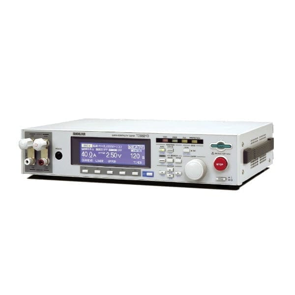
Ground Bond tester supporting standard compliance tests up to 60A
While inheriting the basic performance and functions of its predecessor (TOS6200), such as a constant current driving system that provides current waveforms with little skew and high measurement accuracy, the TOS6210 tester extends the maximum test current from 30 A to 60 A, which is demanded by the new standard. In addition, the tester also lets you judge the acceptability of the device under test based on the drop in voltage, as required in the standard.
What’s more, you can preset test conditions of up to 20 different types of safety standards, such as those for information technology equip- ment, home appliances, medical devices, and measuring in- struments, in the memory on the main unit’s panel. A simple memory call operation allows you to set up a pro- tective earth or protective bonding continuity test as stipu- lated in UL and other relevant specifications including IEC and JIS standards. The tester also features a set of functions that meet the specific needs of testing personnel, such as an offset cancellation function and a memo function that allows you to input calibration dates, production numbers, and other test-related information and read the input information later via the GPIB or RS232C interface.
Ground Bond Tester
Model:
TOS6210
Maker:
KIKUSUI ELECTRONICS CORPORATION
Features
- Test current value: 6 A to 60 A AC / Resistance value: 0.001 Ω to 0.600 Ω
- Voltage drop-based judgment function
- Offset cancelling function
- Stores 100 test conditions in memory
- Incorporates test conditions into program
- Contact check function
- Equipped with standard GPIB and RS232C interfaces
- Equipped with standard test lead (TL12-TOS)
Specifications
Output
| Current setting range *1 4 | Resolution 6.0 to 62.0 A AC (With respect to resistance resulting in output power of the maximum rated Output or less and an output terminal voltage of 5.4 V or less) | |
|---|---|---|
| Resolution | 0.1 A | |
| Accuracy | ± (1% of setting + 0.4A) | |
| Maximum rated output | 220 VA (at the output terminals) | |
| Distortion Rate | 2% or less (with respect to 0.1 Ω pure resistance load of 20 A or greater) | |
| Frequency | 50/60 Hz, sine wave (selectable) | |
| Accuracy | ±200 ppm | |
| Open terminal voltage | 6 Vrms or less | |
| Output method | PWM switching | |
Output ammeter
| Measurement range | AC 0.0A to 66.0A |
|---|---|
| Resolution / Accuracy | 0.1A / ± (1% of reading + 0.4A) |
| Response | Mean value response/rms value display (response time: 200 ms) |
| Hold function | The current measured at the end of test is held during the PASS or FAIL inteval |
Output voltmeter
| Measurement range | 0.00 to 6.00 V AC |
|---|---|
| Resolution / Accuracy | 0.01V / ± (1% of reading + 0.02V) |
| Offset cancel function | 0.00 to 5.40 V (Offset ON/OFF function provided) |
| Response | Mean value response/rms value display (response time: 200 ms) |
| Hold function | The voltage measured at the end of test is held during the PASS or FAIL inteval |
Ohmmeter *2
| Measurement range | 0.001 to 0.600 Ω |
|---|---|
| Resolution / Accuracy | 0.001 Ω / ± (2% of reading + 0.003 Ω) |
| Offset cancel function | 0.000 to 0.600 Ω (Offset ON/OFF function provided) |
| Hold function | The resistance measured at the end of test is held during the PASS or FAIL interval |
Pass/fail judgement function *3
| Resistance value-based judgement |
Window comparator system
|
|
|---|---|---|
| Setting range for the upper reference value (UPPER) | 0.001 to 0.600 Ω | |
| Setting range for the lower reference value (LOWER) | 0.001 to 0.600 Ω | |
| Resolution | 0.001Ω | |
| Judgment accuracy | ± (2% of UPPER + 0.003 Ω) | |
| Sampled voltage value-based judgment |
Window comparator system
|
|
| Setting range for the upper reference value (UPPER) *4 | 0.01 to 5.40 V | |
| Setting range for the lower reference value (LOWER) | 0.01 to 5.40 V | |
| Resolution | 0.01V | |
| Judgment accuracy | ± (2% of setting + 0.05 V) | |
| Calibration | Calibration is performed with the rms value of the sine wave, using a pure resistance load. | |
| LED | PASS | Lights for approximately 0.2 sec when the measured value has been judged as PASS. It is lit continuously when the PASS holding time is set to HOLD. |
| UPPER FAIL | Lights if a resistance or voltage value equal to or greater than the upper reference value is detected and judged FAIL. | |
| LOWER FAIL | Lights if a resistance or voltage value equal to or greater than the upper reference value is detected and judged FAIL. | |
| Buzzer |
The buzzer sounds for the pass holding time has been set if the measured value has been judged as PASS.
|
|
Time
| Test time | Setting range | 0.3 to 999 s Timer ON/OFF function is available. |
|---|---|---|
| Accuracy | ± (100ppm of setting + 20ms) |
Environment
| Operating environment | Indoor use, overvoltage category II | |
|---|---|---|
| Spec guaranteed range | Temperature | 5° to 35°C |
| Humidity | 20 %rh to 80 %rh (non condensing) | |
| Operating range | Temperature | 0° to 40°C |
| Humidity | 20 %rh to 80 %rh (non condensing) | |
| Storage range | Temperature | -20° to 70°C |
| Humidity | 90 % rh or less (no condensation) | |
| Altitude | Up to 2000 m | |
Power supply
| Input voltage range | 85 to 250 V AC | |
|---|---|---|
| Power consumption | At no load (READY) | 60 VA or less |
| Rated load | 420 VA max. | |
| Input frequency range | 47 Hz to 63 Hz | |
| Insulation resistance | 30M min. (500 Vdc), between AC line and chassis | |
| Withstanding voltage | 1390 Vac (2 seconds), between AC line and chassis | |
| Ground bond | 25 Aac/ 0.1 Ω max | |
Safety *5 Conforms to the requirements of the following directive and standard.
| Safety | Low Voltage Directive 2014/35/EU *5 EN 61010-1 (Class I, Pollution degree 2) | |
|---|---|---|
Electromagnetic compatibility (EMC) *5 *6 Conforms to the requirements of the following directive and standard.
| Electromagnetic compatibility (EMC) | EMC Directive 2014/30/EU EN 61326-1 (Class A) EN 55011 (Class A, Group 1) EN 61000-3-2 EN 61000-3-3 Under following conditions
|
|---|
Accessories
| Accessories | AC power cord: 1 piece, Test leadwire TL12-TOS: 1 set, Short bar: 2 pieces (These are inserted between the OUTPUT and SAMPLING terminals.), AC power fuse: 2 pieces (2, including one spare in the fuse holder), Operation manual: 1 copy |
|---|
*1 Time limitation with respect to output. The heat radiation capacity at the output block of the tester is designed to be one-third of the rated output, accounting for size, weight, cost, and other factors. Always use the tester within the limitation values given below. Use of the tester beyond these limits will cause the temperature of the output block to rise excessively, potentially tripping the internal protection circuit. In this case, suspend testing for approximately 30 minutes, then press the STOP switch. When temperatures fall to normal levels, the tester will revert to ready status.
| Ambient temperature t (°C) | Test current I (A) | Pause time | Maximum allowable continuous test time |
|---|---|---|---|
| t ≤ 40° | 40 < I ≤ 60 | Equal to or greater than the test time | ≤ 10 minutes |
| 20 < I ≤ 40 | Equal to or greater than the test time | ≤ 30 minutes | |
| I ≤ 20 | Not required | Continuous output possible |
*2 About ohmmeter’s response time. A resistance value is instantaneously obtained, calculated using the measured voltage and current values. The response time of the ohmmeter complies with the response times of the voltmeter and ammeter.
*3 Resistance value-based and sampled voltage value-based judgments cannot be simultaneously conducted.
*4 Limited by the maximum rated output and the output terminal voltage. The tester can be used within the range shown below.
*5 Not applicable to custom order models.
*6 Only on models that have CE marking on the panel.

To view the pdf files, the Adobe Reader from Adobe Systems is required.