






This website uses cookies so that we can provide you with the best user experience possible. Cookie information is stored in your browser and performs functions such as recognising you when you return to our website and helping our team to understand which sections of the website you find most interesting and useful.


ITEMLIST
Products Infomation

- Kategori Produk
- Electronic Measuring Instruments
- Electrical Safety Testers / Measuring Instruments
- KIKUSUI AC Hipot Tester TOS5200
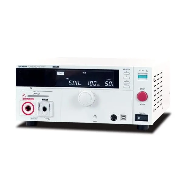
An ideal AC Hipot Tester with low cost of ownership realized, built on more than 50 years of experience in market
TOS5200 dirancang untuk AC Hipot Test dengan kapasitas 500 VA dan 200 mA short circuit current output capability. Dilengkapi dengan amplifier PWM, TOS5200 dapat memberikan output yang stabil & handal tanpa terpengaruh oleh saluran listrik AC. Oleh karena itu, ini adalah solusi sempurna untuk peralatan atau perangkat elektronik yang memenuhi persyaratan IEC, EN, UL, VDE, dan JIS dll.
Karena TOS5200 mencakup sebagian besar fitur model kelas atas kami untuk AC Hipot TestC, TOS5200 mencapai rasio biaya / kinerja yang luar biasa bagi mereka yang membutuhkan kapasitas 200 VA atau 500 VA, atau keduanya. Selain itu, karena melengkapi fungsi Interlock bersama dengan fitur keselamatan lainnya, operator dapat melakukan pengujian dengan nilai arus yang lebih tinggi di brankas.
AC Hipot Tester
Model:
TOS5200
Maker:
KIKUSUI ELECTRONICS CORPORATION
Fitur
- Highly stable output thanks to PWM amplifier
- AC withstand voltage test of 5 kV/100 mA (500 VA)
- High accuracy measurements of ±1.5% of reading (at 500V or more for voltmeter and 1mA or more for ammeter)
- Rise/fall time control
- Key lock & actuator cover
- Equipped with RS232C and USB Interface
Comparison with conventional product TOS5050A (differences)
| Specification comparison item | TOS5200 | TOS5050A | |
|---|---|---|---|
| Test voltage | Output method | PWM switching amp system | Slide transformer method |
| Distortion | 3 % or less | As per commercial power supply waveform | |
| Frequency | 50 Hz or 60 Hz | Synchronized with commercial power supply waveform | |
| Output voltage waveform | Sine | Commercial power supply waveform | |
| Voltage regulation | 10 % or less | 15 % or less | |
| Input voltage variation | ±0.3 % | – | |
| Test time | Minimum setting value | 0.1 s | 0.5 s |
| Accuracy | ±(100 ppm + 20 ms) excluding Fall Time | ±(100 ppm + 20 ms) | |
| Judgment feature | Upper limit setting | AC: 0.01 mA to 110 mA | AC: 0.1 mA to 110 mA |
| Lower limit setting | AC: 0.01 mA to 110 mA | AC: 0.1 mA to 110 mA | |
| Accuracy | 1.00 mA ≤ i: ±(1.5 % of set), i <1.00 mA: ±(1.5 % of set +30 μA) |
Upper limit: ±(5 % + 20 μA) | |
| Rise Time and Fall Time control features | 3 | – | |
| Voltmeter | Display | Digital | Digital, analog |
| Measurement accuracy | ±1.5 % of reading (V>500V) | ±1.5 % f.s | |
| Voltmeter/Ammeter | Measurement method | True rms/mean-value | Mean-value/rms value |
| RS232C Interface | POWER Switch and all function except Key lock | Output for data, test result | |
| Weight | Approx. 14 kg (30.9 lbs) | Approx. 15 kg (33.07 lbs) | |
| Other | Input power supply | 100 Vac to 240 Vac | 100 V ± 10 % |
Spesifikasi
| AC Output section | Output range | 0.05 kV to 5.00 kV | |
|---|---|---|---|
| Setting accuracy | ± (2 % of set + 20 V) when no load is connected | ||
| Setting range | 0.00 kV to 5.50 kV | ||
| Resolution | 10 V STEP | ||
| Max. rated output *1 | 500 VA (5 kV/100 mA) | ||
| Max. rated voltage | 5 kV | ||
| Max. rated current | 100 mA (when the output voltage is 0.5 kV or greater) | ||
| Transformer rating | 500 VA | ||
| Output voltage waveform*2 | Sine | ||
| Distortion | If the output voltage is 0.5 kV or more: 3 % or less (when no load or a pure resistive load is connected) | ||
| Crest factor | √ 2 ± 3 % less than (when the output voltage is 800 V or greater, no load) | ||
| Frequency | 50 Hz or 60 Hz | ||
| Accuracy | ± 0.5 % (excluding during voltage rise time) | ||
| Voltage regulation | 10 % or less (when changing from maximum rated load to no load) | ||
| Input voltage variation | ±0.3 % (5 kV when no load is connected; power supply voltage: 90 V to 250 V) | ||
| Short-circuit current | 200 mA or more (when the output voltage is 1.0 kV or greater) | ||
| Output method | PWM switching | ||
| Start voltage | The voltage at the start of withstanding voltage tests can be set to 50 % of the test voltage. | ||
| Limit voltage | The test voltage upper limit can be set . AC: 0.00 kV to 5.50 kV | ||
| Output voltage monitor function | If output voltage exceeds the specified value + 350 V or is lower than the specified value – 350 V, output is turned off, and protective features are activated. | ||
| Voltmeter | Digital | Measurement range | 0.000 kV to 6.500 kV AC |
| Display | □ . □□□ kV | ||
| Accuracy | V < 500 V:± (1.5 % of reading + 20 V)、V ≧ 500 V: ±1.5 % of reading | ||
| Response*3 | True rms, Average value response/rms display switchable | ||
| Hold feature | After a test is finished, the measured voltage is retained until the PASS or FAIL judgment is cleared. | ||
| Ammeter | Digital | Measurement range | AC:0.00 mA to 110 mA |
| Display | i = measured current i < 1 mA:□ . □□□ mA 1 mA ≦ i < 10 mA:□ . □□□ mA 10mA ≦ i < 100 mA:□□ . □□ mA 100 mA ≦ i:□□□ . □ mA |
||
| Accuracy*4 | 1.00 mA ≤ i: ± (1.5 % of reading), i < 1.00 mA: ± (1.5 % of reading + 30 μA) | ||
| Response*3 | True rms, Average value response/rms display switchable | ||
| Hold feature | After a test is finished, the measured current value is retained until the PASS judgment is cleared. | ||
| Judgment feature | Judgment method and judgment operation |
|
|||||||||||||||||||||
|---|---|---|---|---|---|---|---|---|---|---|---|---|---|---|---|---|---|---|---|---|---|---|---|
| Upper limit setting | AC: 0.01 mA to 110 mA | ||||||||||||||||||||||
| Lower limit setting | AC: 0.01 mA to 110 mA / OFF | ||||||||||||||||||||||
| Judgment accuracy *4 | 1.00 mA ≤ i: ± (1.5 % of set), i < 1.00 mA: ± (1.5 % of set + 30 μA) | ||||||||||||||||||||||
| Current detection method | Calculates the current’s true rms value and compares this value with the reference value | ||||||||||||||||||||||
| Calibration | Calibrated with the rms of a sine wave using a pure resistive load | ||||||||||||||||||||||
| Time | Voltage rise time | 0.1 s to 10.0 s | |||||||||||||||||||||
| Resolution | 0.1 s | ||||||||||||||||||||||
| Voltage fall time | 0.1 s / OFF (only enabled when a PASS judgment occurs) | ||||||||||||||||||||||
| Test Time | 0.1 s to 999 s, can be turned off (TIMER OFF) | ||||||||||||||||||||||
| Resolution | 0.1 s to 99.9 s: 0.1 s0 / 100 s to 999 s: 1 s | ||||||||||||||||||||||
| Accuracy | ±(100 ppm + 20 ms) excluding Fall Time | ||||||||||||||||||||||
*1 Regarding the output time limits:
Taking size, weight, and cost into consideration, the heat dissipation capability of the voltage generator that is used for withstanding voltage tests has been designed to be one half that of the rated output. Use the TOS5300 Series within the following limits. If you use the product in a manner that exceeds these limits, the output section may overheat, and the internal protection circuits may be activated. If this happens, stop testing, and wait until the TOS5300 Series returns to its normal temperature.
| Ambient temperature | Upper limit setting | Pause time | Output time | |
|---|---|---|---|---|
| t ≤ 40 °C | AC voltage | 50 mA < i ≤ 110 mA | Greater than or equal to the output time | 30 min. max. |
| i ≤ 50 mA | Not necessary | Continuous output possible | ||
(Output time = voltage rise time + test time + voltage fall time)
*2: Regarding the test voltage waveform: Waveform distortions may occur if an DUT whose capacitance is dependent on voltage (for example, an DUT that consists of ceramic capacitors) is connected as the load. However, if the test voltage is 1.5 kV, the effect of a capacitance of 1000 pF or less can be ignored.Because the product’s high-voltage power supply uses the PWM switching method, if the test voltage is 500 V or less, the switching and spike noise proportions are large. The lower the test voltage, the greater the waveform is distorted. *3: For both True rms and Mean-value response, 50 ms or above response time is required to satisfy the measurement accuracy. *4: Regarding ammeter and judgment accuracy: During AC withstanding voltage tests, current also flows in the stray capacitance of items such as the measurement leads and jigs. This current that flows in the stray capacitances is added to the current that flows in the DUT, and the sum of these currents is measured.Especially if you want to perform judgments with high sensitivity and accuracy, it is necessary to consider methods to limit the current that flows in these stray capacitances, such as by adding upper and lower limits.
| Output voltage | 1 kV | 2 kV | 5 kV |
|---|---|---|---|
| When using 350 mm long test leads that are suspended in air (TYP) | 2 μA | 4 μA | 10 μA |
| When using the accessory, high test lead TL31-TOS (TYP) | 16 μA | 32 μA | 80 μA |
In case of 70 % humidity or higher, it is considerable to add 50 μA on the Limit value.

To view the pdf files, the Adobe Reader from Adobe Systems is required.