
This website uses cookies so that we can provide you with the best user experience possible. Cookie information is stored in your browser and performs functions such as recognising you when you return to our website and helping our team to understand which sections of the website you find most interesting and useful.


ITEMLIST
Products Infomation

- Kategori Produk
- KEISOKU GIKEN Load Station Series
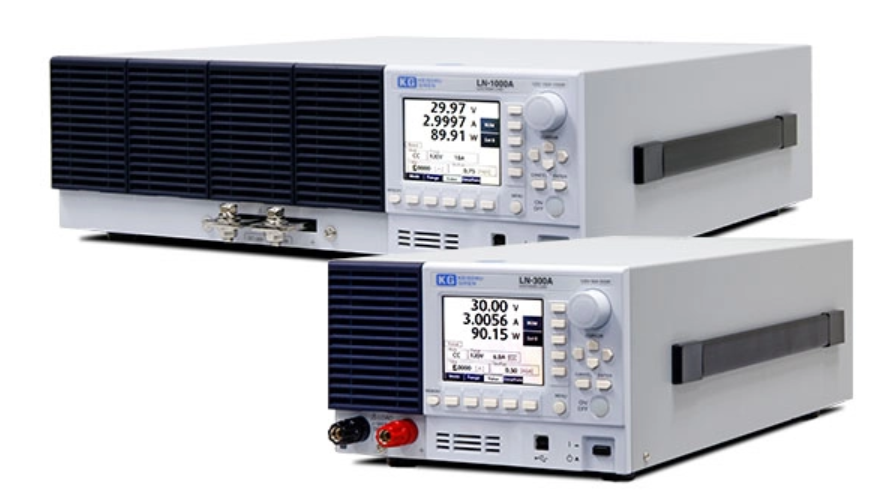
The high-end multifunctional electronic load "Load Station Series" has a lineup of two models with rated voltages of 300W/1000W and 120V/500V respectively
A booster function is standard equipment, so if the capacity of one unit is not enough, it can be easily expanded to 10 units (10 kW for 1 kW type).
Eight front points, such as an easy-to-read 3.5-inch color LCD and large rotary knob, provide oscilloscope-like usability.
Load Station Series
Maker:
KEISOKU GIKEN
Specification
load part
Rating
| LN-300A | LN-300C | |
|---|---|---|
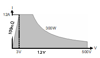
| Voltage | 120V | 500V |
| current | 60A | 12A |
| Power *1 | 300W | |
| Internal minimum resistance *2 | 18 mΩ or less | 100 mΩ or less |
| Load range *2, *3 | 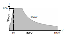 1.08V (60A) / 0.54V (30A) / 0.22V (12A) |
 1.2V(12A) / 0.6V(6A) / 0.28V(2.8A) |
| LN-1000A | LN-1000C | |
|---|---|---|
| Voltage | 120V | 500V |
| current | 180A | 36A |
| Power *1 | 1000W | |
| Internal minimum resistance *2 | 6 mΩ or less | 33.3 mΩ or less |
| Load range *2, *3 | 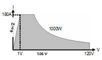 1.08V (180A) / 0.54V (90A) / 0.22V (36A) |
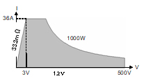 1.2V(36A) / 0.6V(18A) / 0.28V(8.4A) |
*1: Varies depending on the temperature inside the case and operating time when using this product. *2: At the rear panel load terminals. It is not the set value of CR mode. *3: The minimum operating voltage changes depending on the current value.
load mode
Equipped with 6 load modes.
There are 6 types of load modes and 4 types of operation modes, and 17 load tests are possible with these combinations.
The load mode is equipped with an automatic switching function ( VMode ) according to the specified voltage. When performing a discharge test of a secondary battery, etc., the load mode can be switched to prevent overdischarge when the output voltage reaches the set value.
Common to the Load Station series Normal mode (steady load)
| Constant current (CC) mode | A constant current flows even if the load terminal voltage changes |
| Constant resistance (CR) mode | Flows a current proportional to the load terminal voltage |
| Constant voltage (CV) mode | Current is passed so that the load terminal voltage is constant. |
| Constant power (CP) mode | Let the current flow so that the load power is constant |
| External control (EXT) mode | Flows a current proportional to the voltage of the external control input terminal |
| Short mode | Short-circuit the load terminals (maximum current) |
load mode
| load mode | |||||||
|---|---|---|---|---|---|---|---|
| CC | CR | CVs | CP | EXT | SHORT | ||
| action mode | Normal | 〇 | 〇 | 〇 | 〇 | 〇 | 〇 |
| Dynamic | 〇 | 〇 | 〇 | 〇 | ― | ― | |
| *Sequence | 〇 | 〇 | 〇 | 〇 | ― | ― | |
| Sweep | 〇 | 〇 | ― | 〇 | ― | ― | |
*Sequence operation requires setting from a PC.
Automatic switching function (VMode)
| Starting load mode | |||||||
|---|---|---|---|---|---|---|---|
| CC | CR | CVs | CP | EXT | SHORT | ||
| switch mode | OFF | 〇 | 〇 | 〇 | 〇 | × | × |
| ※CC | ― | × | × | × | × | × | |
| CR | 〇 | ― | 〇 | 〇 | × | × | |
| CVs | 〇 | 〇 | ― | 〇 | × | × | |
| CP | 〇 | 〇 | 〇 | ― | × | × | |
*Switching to CC mode is not possible.
Constant current (CC) mode
| LN-300A | LN-300C | LN-1000A | LN-1000C | ||
|---|---|---|---|---|---|
| Current setting range | H. | 0A to 60A | 0A to 12A | 0A to 180A | 0A to 36A |
| M. | 0A to 6A | 0A to 1.2A | 0A to 18A | 0A to 3.6A | |
| L. | 0A to 0.6A | 0A to 0.12A | 0A to 1.8A | 0A to 0.36A | |
| resolution | H. | 5 mA | 1mA | 15mA | 3mA |
| M. | 0.5mA | 0.1mA | 1.5mA | 0.3mA | |
| L. | 0.1mA | 0.02mA | 0.3mA | 0.06mA | |
| Setting accuracy *4 | H. | ±{0.2% of set. +25mA +Vin/50kΩ} | ±{0.2% of set. +10mA +Vin/750kΩ} | ±{0.2% of set. +75mA +Vin/16.67kΩ} | ±{0.2% of set. +30mA +Vin/250kΩ} |
| M. | ±{0.2% of set. +12mA +Vin/50kΩ} | ±{0.2% of set. +3mA +Vin/750kΩ} | ±{0.2% of set. +36mA +Vin/16.67kΩ} | ±{0.2% of set. +9mA +Vin/250kΩ} | |
| L. | ±{0.2% of set. +6mA +Vin/50kΩ} | ±{0.2% of set. +2mA +Vin/750kΩ} | ±{0.2% of set. +18mA +Vin/16.67kΩ} | ±{0.2% of set. +6mA +Vin/250kΩ} | |
| Slew rate *5 (current range) |
H. | 0.2A/μs to 20A/μs | 0.01A/μs to 1A/μs | 0.3A/μs to 30A/μs | 0.03A/μs to 3A/μs |
| M. | 0.02A/μs to 2A/μs | 0.001A/μs to 0.1A/μs | 0.03A/μs to 3A/μs | 0.003A/μs to 0.3A/μs | |
| L. | 0.005A/μs to 0.5A/μs | 0.00025A/μs to 0.025A/μs | 0.0075A/μs to 0.75A/μs | 0.00075A/μs to 0.075A/μs | |
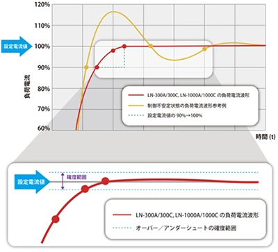
| Startup current over/undershoot range *6 | H/M/L | ±{0.2% of set. ±25mA +Vin/50kΩ} | ±{0.2% of set. ±10mA +Vin/750kΩ} | ±{0.2% of set. ±75mA +Vin/16.67kΩ} | ±{0.2% of set. ±30mA +Vin/250kΩ} |
*4: At an ambient temperature of 23°C ±5°C. *5: At the rear panel load terminals. Load current response speed from 10% to 90% of the time between rise and fall. Can be set only in CC mode and EXT mode. In CV mode, it becomes the response time setting. It cannot be set in CR, CP and SHORT modes. *6: Range of over/undershoot that occurs from 90% to 100% (set current value) of the rising current.
Rising current over/undershoot range
Constant resistance (CR) mode
| LN-300A | LN-300C | LN-1000A | LN-1000C | ||
|---|---|---|---|---|---|
| Voltage range | 20V | 85V | 20V | 85V | |
| Resistance setting range | Current range: H | 40.000S to 0.005S (0.025Ω to 200Ω) |
3.3333S to 0.0004S (0.3Ω to 2.5kΩ) |
120.00S to 0.01S (0.0083Ω to 66.667Ω) |
10.000S to 0.001S (0.1Ω to 833.33Ω) |
| Current range: M | 4.000S to 0.0005S (0.25Ω to 2kΩ) |
0.33333S to 0.00004S (3Ω to 25kΩ) |
12.000S to 0.001S (0.0833Ω to 666.67Ω) |
1.0000S to 0.0001S (1Ω to 8333.3Ω) |
|
| resolution | Current range: H | 4ms | 333 μs | 12ms | 1ms |
| Current range: M | 400 μs | 33 μs | 1.2ms | 0.1ms | |
| CR mode slew rate (typ. value) *7 |
Current range: H | 2.8A/µs | 0.2A/µs | 7.0A/μs | 0.9A/µs |
| LN-300A | LN-300C | LN-1000A | LN-1000C | ||
|---|---|---|---|---|---|
| Voltage range | 120V | 500V | 120V | 500V | |
| Resistance setting range | Current range: H | 13.333S to 0.0016S (0.075Ω to 600Ω) |
1.1111S to 0.0001S (0.9Ω to 7kΩ) |
40.000S to 0.005S (0.025Ω to 200Ω) |
3.3333S to 0.0004S (0.3Ω to 2.3333kΩ) |
| Current range: M | 1.3333S to 0.00016S (0.75Ω to 6kΩ) |
0.11111S to 0.00001S (9Ω to 70kΩ) |
4.0000S to 0.0005S (0.25Ω to 2kΩ) |
0.33330S to 0.00004S (3Ω to 23.333kΩ) |
|
| resolution | Current range: H | 1.33ms | 111 μs | 3.99ms | 333 μs |
| Current range: M | 133 μs | 11 μs | 399 μs | 33 μs | |
| Setting accuracy *8 | ±{0.5% of Conv.Curr.+0.2% of FS .+Vin/50kΩ} | ±{0.5% of Conv.Curr.+0.2% of FS .+Vin/750kΩ} | ±{0.5% of Conv.Curr.+0.2% of FS .+Vin/16.67kΩ} | ±{0.5% of Conv.Curr.+0.2% of FS .+Vin/250kΩ} | |
*7: CR mode slew rate (dynamic mode) LN-300A: at 7.5 V / 5.63 S, LN-300C: at 25 V / 0.48 S, LN-1000A: at 15 V / 12 S, LN-1000C: at 27 V /1.33 S
*8: Conv.Curr. indicates the ideal current value of “Vin / setting resistance value”. It is valid from a voltage value of 1/10 V or more of the voltage range selected by Vin. FS . is the current full scale of current H range. At an ambient temperature of 23°C ±5°C.
Constant voltage (CV) mode
| LN-300A | LN-300C | LN-1000A | LN-1000C | ||
|---|---|---|---|---|---|
| Voltage setting range | H. | 0V to 120V | 0V to 500V | 0V to 120V | 0V to 500V |
| L. | 0V to 20V | 0V to 85V | 0V to 20V | 0V to 85V | |
| resolution | H. | 10mV | 50mV | 10mV | 50mV |
| L. | 2mV | 10mV | 2mV | 10mV | |
| Setting accuracy *9 | ±{0.1% of set. +0.1% of FS .} | ||||
| Response time (typ. value) *10 | Fast/Slow | ||||
| Fast 45ms | Fast 280ms | Fast 550 μs | Fast 110ms | ||
| Response start time (typ. value) *11 | 2ms | 7ms | 20 μs | 4ms | |
*9: At an ambient temperature of 23°C ±5°C. *10: Time to reach CV setting value (dynamic mode, voltage range: L, current range: H) LN-300A: 15.0 V → 7.5 V, LN-300C: 25.0 V → 22.5 V, LN-1000A: 15.0 V → 4.0 V, LN-1000C: 27.0 V → 19.8 V *11: Time from switching CV setting value to starting control Dynamic mode, voltage range: L, current range: H
Constant power (CP) mode
| LN-300A | LN-300C | LN-1000A | LN-1000C | ||
|---|---|---|---|---|---|
| Power setting range | Current range: H | 0W to 300W | 0W to 1000W | ||
| Current range: M | 0W to 40W | 0W to 120W | |||
| resolution | Current range: H | 50mW | 167mW | ||
| Current range: M | 5mW | 16.7 mW | |||
| Setting accuracy *12 | ±{0.6% of set.+1.4% of FS .+(Vin×Vin)/50kΩ} | ±{0.6% of set.+1.4% of FS .+(Vin×Vin)/750kΩ} | ±{0.6% of set.+1.4% of FS .+(Vin×Vin)/16.67 kΩ} | ±{0.6% of set.+1.4% of FS .+(Vin×Vin)/250kΩ} | |
*12: FS is the current full scale of current H range. At an ambient temperature of 23°C ±5°C.
External control (EXT) mode
| LN-300A | LN-300C | LN-1000A | LN-1000C | ||
|---|---|---|---|---|---|
| Current setting range | H. | 0A to 60A | 0A to 12A | 0A to 180A | 0A to 36A |
| M. | 0A to 6A | 0A to 1.2A | 0A to 18A | 0A to 3.6A | |
| resolution | H. | 10mA | 2mA | 30mA | 6mA |
| M. | 1mA | 0.2mA | 3mA | 0.6mA | |
| Setting accuracy *13 | ±{0.2% of set. +0.5% of FS . +Vin/50 kΩ} | ±{0.2% of set. +0.5% of FS . +Vin/750 kΩ} | ±{0.2% of set. +0.5% of FS . +Vin/16.67 kΩ} | ±{0.2% of set. +0.5% of FS . +Vin/250 kΩ} | |
| control voltage | 0V to 10V | ||||
*13: The setting accuracy of the external control mode is only when the control voltage input is 10 V. At an ambient temperature of 23°C ±5°C.
Short mode
| LN-300A | LN-300C | LN-1000A | LN-1000C | |
|---|---|---|---|---|
| Short current (maximum) | 60A | 12A | 180A | 36A |
action mode
Dynamic mode (variable load)
| Common to the Load Station series | |
|---|---|
| control method | Switching operation (executed by sequentially switching between 2 types or up to 16 types of load conditions) |
| Available load mode | CC/CR/CV/CP mode |
| Setting cycle | ~20ms / ~200ms / ~2s / ~20s / ~60s |
| Cycle resolution | 1 μs / 10 μs / 100 μs / 1 ms / 10 ms |
| Action selection | Single (Time only), Repeat |
| Minimum load response time (nominal) *14 | 500 ns (in H/M/L CC mode) |
*14: Minimum response time for slew rate setting. When 50% or more of the rated load current value for each H/M/L range.
About minimum load response time (nominal)
The slew rate of this product may slow down depending on the set load current value. The relationship between slew rate and load current value is called minimum load response time (nominal). Regarding the minimum load response time (nominal), the slew rate may be slower than the set value due to the restrictions and influences of the following conditions.
Terms and Restrictions
- When CC mode and dynamic mode are set
- 50% or more of the rated load current for each H/M/L range
- Load terminal voltage (Vin) or more (Refer to the maximum set slew rate for load terminal voltage in the next section.)
- Reduce the effect of inductance on cabling
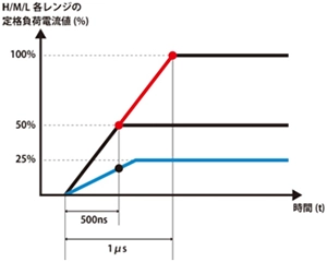
As shown in the figure above, when the slew rate is set at 50% or more of the rated load current of each H/M/L range, the waveform of the set slew rate is obtained. If the load current is less than 50% of the rated load current for each H/M/L range, the value will be lower than the set slew rate.
Maximum set slew rate at load terminal voltage
| model | Load terminal voltage Vin (rear panel) | Maximum set slew rate |
|---|---|---|
| LN-300A | 6V≤Vin | 20A/μs |
| 5V≤Vin | 15A/μs | |
| 4V≤Vin | 10A/μs | |
| 3V≤Vin | 5A/μs | |
| LN-300C | 3V≤Vin | 1A/μs |
| model | Load terminal voltage Vin (rear panel) | Maximum set slew rate |
|---|---|---|
| LN-1000A | 8V≤Vin | 30A/μs |
| 7V≤Vin | 20A/μs | |
| 5V≤Vin | 10A/μs | |
| 3V≤Vin | 5A/μs | |
| LN-1000C | 3V≤Vin | 3A/μs |
sweep mode
| Common to the Load Station series | |
|---|---|
| Sweep R (VI characteristic test) | Measure the current and voltage while changing the load in CR mode |
| Sweep C (overcurrent characteristic test) | Measure current and voltage values while changing the load in CC mode |
| Sweep P (overpower characteristic test) | Measure power and voltage values while changing the load in CP mode |
Sequence operation (remote control only)
| Common to the Load Station series | |
|---|---|
| enabled mode | CC/CR/CV/CP mode |
| Maximum number of steps | 1024 |
| step time | 1 ms to 10 min (common for each step) |
| Step time resolution | 1 ms (1 ms to 100 ms) / 100 ms (100 ms to 10 min) |
| number of repetitions | 1 to 65535, or ∞ |
![]()
To view the pdf files, the Adobe Reader from Adobe Systems is required.