
This website uses cookies so that we can provide you with the best user experience possible. Cookie information is stored in your browser and performs functions such as recognising you when you return to our website and helping our team to understand which sections of the website you find most interesting and useful.


ITEMLIST
Products Infomation

- Kategori Produk
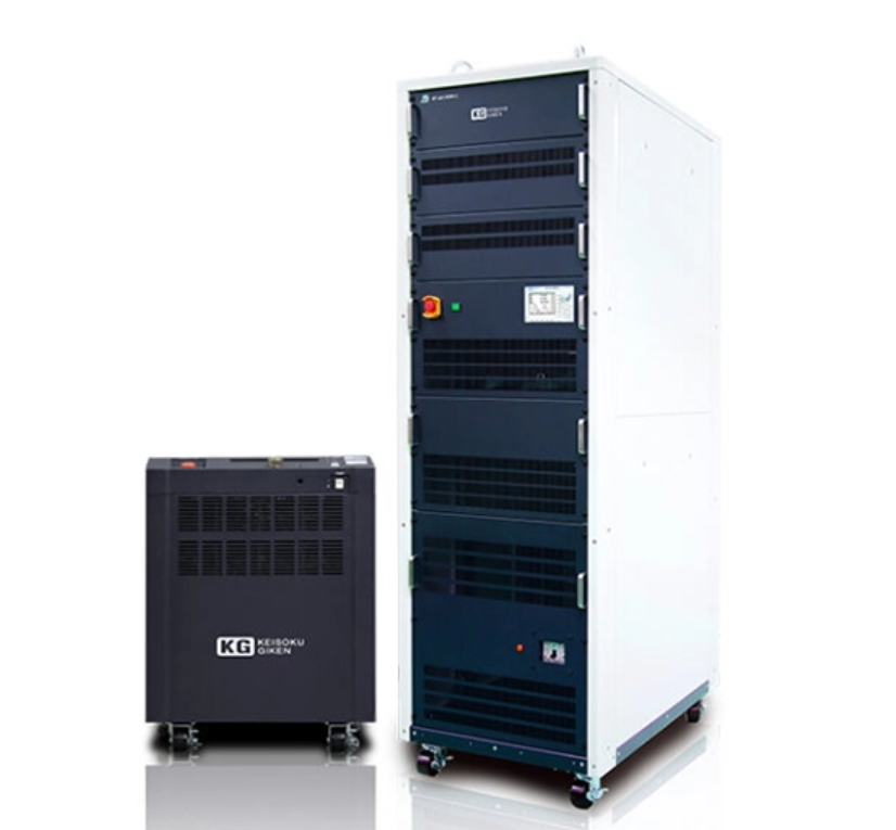
- KEISOKU GIKEN Ene-phant series regenerative electronic load 10kW/50kW
Can be used as AC electronic load and DC electronic load.
It is a multi-phase electronic load that can be used according to the usage scene. With capacity expansion by combining multiple units, the system configuration can be freely configured. Equipped with value that is required only for long-term use. It is an electronic load that looks ahead. The capacity can be expanded up to 10kW/50kW for a single unit, and up to 50kW/250kW (single-phase 2-wire/single-phase 3-wire/three-phase 3-wire) by parallel connection.
Ene-phant series regenerative electronic load 10kW/50kW
Maker:
KEISOKU GIKEN
Feature
Frequency 1000Hz compatible (10kW model only)
(Factory option: AX-OP18)
Works seamlessly from 5Hz to 1,000Hz
It responds from 5Hz, which is the low frequency range necessary for motor simulation, and supports the base frequency of the motor inverter from 5Hz to 1,000Hz (accuracy guaranteed: 5Hz to 800Hz). This is the only AC electronic load in Japan with a wide band of 5Hz to 1000Hz. (according to our research)
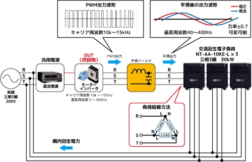
Compatible with motor inverters (PWM output)
It is possible to perform evaluation experiments without using a motor emulator or an actual motor by smoothing the PWM output from the motor inverter with a filter. Also, since it is not a dedicated tester, it can be used for a wide range of experiments as a general-purpose AC electronic load.
Frequency 400Hz compatible (10kW/50kW model)
(factory option)
The standard frequency range is 40 to 70Hz, but if you specify an option, AC 400Hz (380Hz to 420Hz) for aircraft and ships can be supported. Custom-made options are also available for seamless response from 40 to 420 Hz. It can also be applied to the evaluation and testing of industrial motor inverters (a separate smoothing inductance is required).
(Compatible models: NT-AA-10kE-L: AX-OP05, AX-OP15)
(Compatible models: NT-AA-50kE-L: AX-OP14, AX-OP16)
load function
Diverse load modes for both AC and DC
Depending on the model, it supports up to 12 load modes in AC/DC mode.
[Load mode DC]
| model | CC | CR | CVs | CP | CC + CV | CP + CV | MPPT |
|---|---|---|---|---|---|---|---|
| NT-AA-10KE-L | ○ | ○ | ○ | ○ | ー | ー | ○ |
| NT-AD-10KG-L | ○ | ○ | ○ | ○ | ー | ー | ○ |
| NT-AA-50KE-L | ○ | ○ | ○ | ○ | ○ | ○ | ○ |
[Load mode AC]
| model | CC | CR | CP | CF | PE | GCC | GCRMore |
|---|---|---|---|---|---|---|---|
| NT-AA-10KE-L | ○ | ○ | ○ | ○ | ○ | ○ | ○ |
| NT-AA-50KE-L | ○ | ○ | ○ | ー | ○ | ー | ー |
Compatible with high voltage
In order to support a wide range of output load tests for various high-voltage equipment that accompanies the increasing voltage of electronic components, a maximum of 1500V is supported with one unit, and up to 1500V with two units connected in series .
direct current
| model | Low range | high range |
|---|---|---|
| NT-AA-10KE-L | 70 to 340V | 140-680V |
| NT-AA-50KE-L | 20-750V (40-1500V) | |
Alternating current
| model | Low range | high range |
|---|---|---|
| NT-AA-10KE-L | 50-240V | 100-480V |
| NT-AA-50KE-L | 20 to 350 Vrms | |
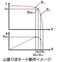
MPPT mode
Equipped with MPPT mode (hill-climbing method*) that allows you to directly connect PV panels and test IV characteristics, etc. *A control method that continuously adjusts the operating voltage and current until the maximum power is obtained.
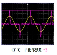
CF mode (crest factor setting)
The crest factor (crest factor) can be arbitrarily set in the range of 1.4 (sine wave) to 4.0 in steps of 0.1. This enables testing that reproduces the crest factor of a capacitor input type switching power supply.
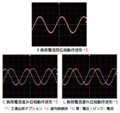
PF mode (advance/lag current phase setting)
Capacitive load (C), resistive load (R), and inductive load (L) can be simulated with one unit. The phase can be set in the range of -90deg to +90deg, and can also be set by power factor. Best suited as an inverter output load.
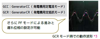
GCC/GCR mode
(Factory option for generator output: AX-OP10)
Even if the output waveform contains distortion like an engine generator, the new load modes GCC and GCR can stably take the load.
Grid connection (regeneration)
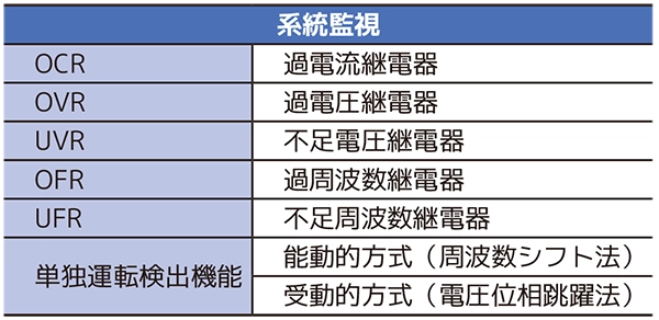
Compliant with grid connection regulations
Equipped with system monitoring and protection functions that comply with the grid connection protection device certification test, it has the same monitoring and protection functions as general commercial power conditioners, and can circulate energy safely and without waste. can. Various system monitoring functions can be set to arbitrary values.
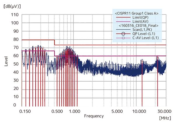
Regenerative power noise CISPR Class A compliant
Regenerative power noise complies with Class A. It has low noise so that there is no influence such as operation failure on other devices due to regenerative power noise.
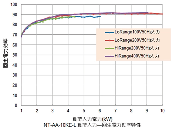
Regeneration efficiency of 90% or more, the highest level in the industry
Achieves high efficiency of 90% or more (at rated load). Furthermore, if the rated power is 15% or more, a regenerative efficiency of 80% or more is achieved. Highly efficient regeneration is possible over a wide range of load power.
Grid side power measurement
(Factory option: AX-OP08)
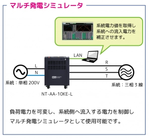
Integral power and active power (instantaneous power) on the grid side can be measured. By applying this function, it can be used as a multi-generation simulator by varying the load power and controlling and correcting the power flowing into the grid. Since power generation can be simulated by software, it is ideal for demonstration experiments of smart grids. (Compatible model: NT-AA-10KE-L)
Employs electrical insulation using a transformer
Electric insulation between the electronic load and the grid is provided by a transformer. Safe and secure design.
Grid side single-phase three-wire input voltage selection
(Factory option: AX-OP10)
The input voltage can be changed to the single-phase 3-wire (single-phase 2-wire connection possible) method. In addition, 3-phase 4-wire 220V, 230V, etc. can be customized. (Compatible model: NT-AA-10KE-L)
User interface
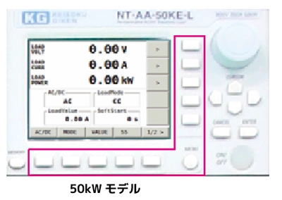
Easy to use and simple dial operation
Equipped with a large dial (rotary knob) that allows comfortable operation of various functions and settings. We focused on intuitive operation and made it as simple as possible.
Oscilloscope-like operability
Adopts oscilloscope button layout and operability. The function pasted on the button image on the LCD screen is switched, enabling intuitive operation.
Emergency stop button
Equipped with an emergency stop button, which is essential in the car electronics industry. During operation, the power line gate is blocked (forced open by conductor). 10kW and 50kW are equipped with guards to prevent malfunction, and external control (Di input) is also possible.

interface
rich interface
RS-232C, LAN (Ethernet), and PLC interfaces are commonly equipped as standard, allowing remote control including automation from a host PC. In addition, the 10kW model is equipped with USB as standard. GP-IB (AX-OP04) can also be selected as an option.
| model | LANs | USB | RS-232C | GP-IB | Di/Do | Ai |
|---|---|---|---|---|---|---|
| NT-AA-10KE-L | ○ | ○ | ○ | ○* | ○ | ○ |
| NT-AA-50KE-L | ○ | ー | ○ | ー | ○ | ○ |
*: Factory option
Analog input signal (Ai): CC / CP / current phase setting Digital input signal (Di): Load ON / OFF Digital output signal (Do): Various alarms
Voltage, current monitor
(Option: AX-OP03 10kW model only, 50kW is equipped as standard)
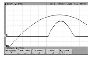
As an option, voltage and current monitoring (waveform observation with an oscilloscope, etc.) is possible with a BNC connector (insulated).
Voltage 10V/1000V/50Ω BNC terminal/isolated output
Current 10V/200A/50Ω BNC terminal/isolated output
others
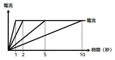
Soft start function
You can choose from 4 types of time settings until the current rises: 1 second, 2 seconds, 5 seconds, and 10 seconds.
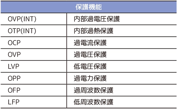
Body protection function
As a protection function of the electronic load device, 8 types of protection circuits are implemented to support safe test operation.
Adjuster fixing bracket convenient for anti-seismic measures
(Option: AX-OP09 10kW model only)
An adjuster fixing bracket is available as an option. Since the unit can be fixed by directly driving it into the floor with an anchor bolt, it can be used as an earthquake countermeasure.

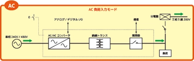
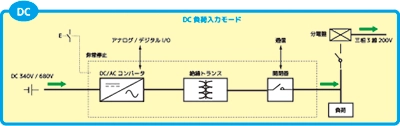
Single line schematic diagram
Single connection diagrams for AC and DC modes are shown.
Supports up to 1,500 V by series operation
(50kW model: option)
Using a wide range of DC inputs, it can be used as a multi-power interface inverter. Up to two units can be connected in series, and can support input voltages up to 1500V and maximum capacity of 100kW. There is also a model (maximum 250kW) that supports 1500V with one 50KW unit.
Extended capacity up to 250kW (50kW model)
3 master-slave configuration with 3-phase 150kW, 5 units can be combined to expand to a maximum of 250kW. It can be used for testing quick chargers and large-capacity EV batteries.
![]()
To view the pdf files, the Adobe Reader from Adobe Systems is required.