






This website uses cookies so that we can provide you with the best user experience possible. Cookie information is stored in your browser and performs functions such as recognising you when you return to our website and helping our team to understand which sections of the website you find most interesting and useful.

ITEMLIST
Products Infomation

- Kategori Produk
- Electronic Measuring Instruments
- Oscilloscopes
- GRAPHTEC IWATSU Digital Oscilloscopes DS-5600A Series
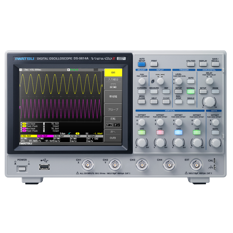
Extended basic functionality, making it easier to use
Bandwidth100~500MHz
2 GS/s 4/2 Channels Max
Up to 5M points
Digital Oscilloscopes
Model:
DS-5600A Series
Maker:
GRAPHTEC IWATSU Test Instruments Co., Ltd.
Features
DS-5600A Series All models 50 Ohm input compatible
Supports a wide variety of probes.
AUX OUT output terminal is equipped as standard.
In addition to the effective trigger signal output, the Pass/Fail determination function can output when the result becomes a Pass or Fail.
High Resolution
When measured at a sampling speed lower than the highest sampling speed, the data captured in the highest sampling can be averaged to capture waveforms, reduce random noise and increase vertical axis resolution to up to 12 bits equivalent equally.
Expanded average count
The average setting count was expanded from 256 times to 65536 times (maximum). This can effectively reduce non-periodic random signals from repeated measured signals.
Auto setup disable toggle function
Prevents the panel settings from being updated, even if the AUTO SET button is pressed by mistake.
Long memory up to 5M points (when all channels are used: 2.5m points/CH)
You can capture long waveforms while maintaining fast sampling.
4 item simultaneous judgment of waveform parameters/waveform mask judgment function
Automatic measurement of waveform parameters logging function (list display)
The pass/fail judgment can be performed automatically depending on the value of the mask or waveform parameter.
By performing 4 items at the same time, it is possible to set strict conditions.
Automatic measurement of waveform parameters logging function (list display)
Up to four waveform parameters can be logged. Logged data can be saved to a USB memory device. By importing data into Excel, etc., you can easily display the histogram (variable distribution) and trend display (change over time) of waveform parameters.
Full cycle parameter measurement*
Automatically measures the waveform of the captured full cycle (time axis). A large amount of data can be captured in the long memory to determine the maximum and minimum deflection widths. You can also analyze the interval that is pinched by the cursor.
* The waveform parameter of the vertical axis (voltage axis) displays the measured value once per sweep.
Enhanced trigger capability
The trigger function is enhanced and waveforms can be triggered under optimal conditions, even in logic signals and serial data signals with increased complexity.
Complex setting items performed by pattern triggering can also be set smoothly thanks to the operability of the touch screen.
Waveform operation function
Two waveforms can be added, subtracted, multiplied, and channel waveform frequency analysis (FFT) can be performed.
The DS-5600A/5600 Series supports differentiation and integration operations.
The operation waveform can be saved as data and set as the source for automated measurement of waveform parameters.
- Addition and subtraction: evaluation of differential signals
- Multiplication: Evaluation of power waveform by voltage x current
- FFT: Analysis in the frequency range such as periodic noise and vibration
Probe selection function
When you select a model of an IWATSU ELECTRIC probe, the attenuation ratio and coupling are set automatically. The model number, vertical range bandwidth, and input coupling are displayed.
CH-to-CH skew adjustment function
The skew can be adjusted up to 500ns.*
For example, the phase adjustment between the current probe and the voltage probe allows for more accurate power waveform operations.
* When the horizontal axis is set to skew priority (there is a limit to the number of waveforms in the replay function).
Clear sweep function
You can reset the measured data such as replay waveform, averaging, persistence, automatic measurement of waveform parameters, pass/fail judgment, and logging.
High-speed remote waveform transfer
It achieves a remote transfer rate of about 100 times that of previous models.*
When collecting measurement inspection data remotely, you can reduce tact time and increase production efficiency.
* When the waveform display mode is turned OFF when the LAN interface is used. It is a measurement result under specific conditions, and the value is a reference. Actual transfer time will vary depending on the specifications of your PC.
Touchscreen independent keys/knobs
The 7.5-inch color LCD is equipped with a touchscreen function for intuitive operation.Although it is a compact size, the CH/MATH independent operation keys and knobs have been adopted to achieve one-action comfort.
Peak detection function
It can reliably capture noise (minimum 1ns pulse width) in very slow signals.
Rescale function
By measuring with current probes, shunt resistance, various sensors, etc., the obtained output voltage signal can be converted into each value and read directly.
Automatic measurement of waveform parameters (full cycle measurement of horizontal axis parameters)
You can choose from up to four of 26 waveform parameters to display. You can also display the maximum, minimum, and number of measurements. The cursor function also supports automatic measurement of a limited range. You can further expand the range of analysis by using the judgment function and logging function.
Simple Moving Average
Simple Moving Average (SMA) is a digital filter that can be configured per-channel to reduce noise by smoothing the sampling points at a specified width.
* It can also be used with single-shot signals that are not repeating signals.
The PNG format of the image data storage format is compatible with transparent type
Supports the transparent attributes of PNG, when creating a document using a PC, the waveforms can be stacked with transparency.
Specifications
Digital Oscilloscope “ViewGo II” DS-5600A Series Specifications
| 500MHzModel | 350MHzModel | 200MHzModel | 100MHzModel | ||||||
|---|---|---|---|---|---|---|---|---|---|
| DS-5654A | DS-5652A | DS-5634A | DS-5632A | DS-5624A | DS-5622A | DS-5614A | DS-5612A | ||
| Rise time (Representative values) |
750ps | 1ns | 1.75ns | 3.5ns | |||||
| Number of input channels | 4 | 2 | 4 | 2 | 4 | 2 | 8 | 2 | |
| Frequency bandwidth (-3dB) | 500MHz | 350MHz | 200MHz | 100MHz | |||||
| Maximum sampling speed | 2GS/s (when channels are coupled), 1GS/s (when all channels are used) | ||||||||
| Equivalent sampling speed | 100GS/s | ||||||||
| Peak detection resolution | 1ns | ||||||||
| Averaging function | 2 to 65536 times (power of 2 steps) | ||||||||
| Averaging Count display function |
Display the number of executions on the screen. | ||||||||
| Memory length | 5M points/ch (when 2 channels are coupled), 2.5M points/ch (all channels) | ||||||||
| Vertical resolution | 8 bits (when high resolution arithmetic is enabled: up to 12 bits) | ||||||||
| Vertical resolution display function | Display the number of resolution bits | ||||||||
| Input voltage range | 2mV/div ~ 10V/div(1MΩ) 2mV/div ~ 2V/div(50Ω) |
||||||||
| Offset voltage | 2mV/div ~ 50mV/div : ±1V、50.2mV/div ~ 500mV/div : ±10V、502mV/div ~ 10V/div : ±100V | ||||||||
| DC gain accuracy | ±(1.5% +0.5% full-scale) | ||||||||
| Maximum input voltage | ±400 Vpeak (1MΩ)、5 Vrms(50Ω) | ||||||||
| Bandwidth limit filter | Analog type:100MHz, 20MHz, 2MHz, 200kHz | Analog type:20MHz, 2MHz, 200kHz | |||||||
| Digital type: Choose either LPF, HPF, or SMA, channel independent | |||||||||
| Input coupling | GND、DC 1MΩ、AC1MΩ、DC50Ω | ||||||||
| Input impedance | 1MΩ±1% //16pF、 50Ω±1% | ||||||||
| Probe sense | Auto search:1:1, 10:1, 100:1, 1000:1 Manual setting:1:1, 5:1, 10:1, 20:1, 50:1, 100:1, 200:1, 500:1, 1000:1, 2000:1 |
||||||||
| Time axis range | 500ps/div ~ 50s/div | 1ns/div ~ 50s/div | 2ns/div ~ 50s/div | 5ns/div ~ 50s/div | |||||
| Standard probe | SS-101R (with standard number of channels) | SS-0130R (with standard number of channels) | |||||||
| Roll mode | 50ms/div ~ 50s/div(100kS/s max) | ||||||||
| Clock accuracy | ±10 ppm | ||||||||
| Power supply/power consumption | AC100V ~ 240V(50Hz / 60Hz), AC100V ~ 120V(400Hz) / 95VA max(60W max) | ||||||||
| Dimensions/Body weight | Approx. 330Wx190Hx124D mm/Approx. 3.7kg | ||||||||
| Performance warranty temperature | 10 ~ 35℃ | ||||||||
| Operating temperature/ humidity/altitude |
Temperature 0 to 40°C/Humidity 5 to 80% RH ≤ 30°C (no condensation), 55% RH or less 40°C (no condensation)/Altitude 2000m or less |
||||||||
| Standard Accessories | Probes (one for each channel), power cord (1), front panel cover (1), manual (CD-ROM) (1), user’s guide (1) | ||||||||
DS-5600A Series Trigger function
| Contents | ||
|---|---|---|
| Trigger function | Edge, Edge Alternate, Edge OR, Number of Pulses, Pulse Width, Period, Missing, TV, Pattern (OR, NOR, AND, NAND), Serial (UART, SPI, I2C) |
|
| TV trigger | standard | NTSC、PAL、Custom |
| Line setting range selection | up to 3000 | |
| Field selection | 1、2、4、8 | |
| Pulse number trigger setting range | 1 to 9999 events | |
| Pulse width trigger time setting range | 15ns~50s | |
| Cycle trigger time setting range | 40ns~50s | |
| Missing (dropout) Trigger time setting range |
50ns~50s | |
| Pattern trigger | OR、NOR、AND、NAND | |
| Trigger source | All channels | |
| State | HIGH、 LOW、 Don’t Care | |
| Threshold level | Independent setting for all channels | |
| Serial trigger UART | Trigger selection | START, STOP,Parity error, data pattern |
| Comparison data length | 5 to 8 bits | |
| Bit rate | 1000bps~1Mbps(Set in 100bps units) | |
| Signal source | CH1~CH4, EXT(2-channel device is CH1, CH2, EXT) | |
| Serial trigger UART | Trigger selection | Data pattern |
| Comparison data length | 4 to 64 bits | |
| CS selection | Positive logic/Negative logic,Idle time specification when there is no CS | |
| Signal source | CH1~CH4, EXT(2-channel device is CH1, CH2, EXT) | |
| * CH1 input is for SCK signal input only: up to 20MHz | ||
| Serial trigger I2C | Trigger selection | START, STOP, RESTART, NACK,Data pattern |
| Comparison data length | 7-bit/10-bit address, 1 to 5 bytes,EEPROM read, byte (shift comparison available) | |
| Address mode | Choose from 7-bit/10-bit/EEPROM read | |
| Signal source | CH1~CH4, EXT(2-channel device is CH1, CH2, EXT) | |
| Trigger source | All channels, EXT (±0.5V), EXT10 (±5.0V), line | |
| Trigger slope | Positive, negative | |
| Coupling | AC, DC, high frequency removal, low frequency removal, noise removal | |
Display/Resolution
| Contents | |
|---|---|
| Display | 7.5-inch color TFT LCD (touch screen) |
| Resolution | VGA:640 × 480 pixels |
| Display format | YT, XY, XY Trigger |
| Vector connection | Sample point interpolation display, dot display |
| Analog persistence | Solid tone display, spectrum display |
| Persistence Display time | 100ms, 200ms, 500ms, 1s, 2s, 5s, 10s,Infinite |
| Save internal waveform(REF memory) | 5 waveforms |
| Front panel settings save | Five settings can be saved in the internal memory or USB memory device |
| AUTO SETUP function | Can be set to Enabled or Disabled |
Parameter measurement, cursor, zoom, math, replay
| Contents | |
|---|---|
| Parameter measurement | Maximum value, minimum value, peak value, RMS value, cycle RMS value, average value, cycle average value, top, base, top-base, rising overshoot, falling overshoot, rising time 20-80%, falling time 80-20%, rising time 10-90%, falling time 90-10%, frequency, cycle, number of pulses (positive), number of pulses (negative), pulse width (positive), pulse width (negative), duty ratio, integral, skew (positive/negative), skew @ level |
| Number of simultaneous measurements | Maximum 4 parameters |
| Statistical values display | maximum value, minimum value, number of measurements |
| Logging items | Time, parameter measurement results (conditions A, B, C, and D), Pass/Fail judgment results |
| Output destination | When recording: Pop-up screen, internal memory (up to 86,400) after recording: USB memory device |
| Pass/Fail | Judgment mode: parameter judgment or mask determination, judgment result: USB save, BEEP sound, pulse output, logging Page search function: select Pass or Fail, search forward or backward |
| Cursor | Time, Amplitude, Time & Amplitude, Value at Cursor |
| Zoom | Press the Zoom button on the front panel to display the magnified waveform in a different grid |
| Math function | Addition, subtraction, multiplication, differentiation, integration, FFT (up to 8k points, rectangular, Hanning, flat top window function) Double operation by either differential, integral, or FFT from the result of either addition, subtraction, or multiplication (9 patterns) |
| Rescale | a * x + b (x: input voltage, a, b: user-defined) |
| unit conversion | volt, ampere, watt, °C, no display |
| Replay | Automatic waveform recording, up to 2048 waveforms can be saved and replayed |
| Frequency counter | 6-digit |
| Interface | USB 2.0HS compatible (device, host), LAN (100Base-TX),GPIB (factory option DS-576), AUX interface (connector for external option) |
| AUX OUT | Trigger output and pass/fail judgment output can be switched |
| Waveform data save | Save to USB memory device with binary, ASCII, Mathcad, arithmetic (ASCII), and arithmetic (Mathcad) |
| Hard copy output | Save the image to a USB memory device in TIFF, BMP, or PNG (Transparent) format or output to a PictBridge® -compatible printer |
| Calibration signal output | Square wave 1kHz, 3Vp-p |
Option
| Contents | |
|---|---|
| AUX IO CH1/CH2 output DS-577 (Factory option) |
AUX IO1: Output CH1 input signal with offset voltage added AUX IO2: Output CH2 input signal with offset voltage added |
| AUX IO CH1 output DS-578 (Factory option) |
Aux IO1: Output CH1 input signal with offset voltage added |
| GPIB interface DS-576 (Factory option) |
GPIB: IEEE488.2 |
| Probe power supply DS-579 | IWATSU ELECTRIC active probe power supply 2 Series |

To view the pdf files, the Adobe Reader from Adobe Systems is required.