This website uses cookies so that we can provide you with the best user experience possible. Cookie information is stored in your browser and performs functions such as recognising you when you return to our website and helping our team to understand which sections of the website you find most interesting and useful.


ITEMLIST

- Products by Category
- KIKUSUI Compact High Voltage DC Electronic Load PLZ-5WH2 Series
For evaluation of large-capacity power supplies / large-capacity storage batteries, etc! Testing with hyper-realistic load simulation made possible!
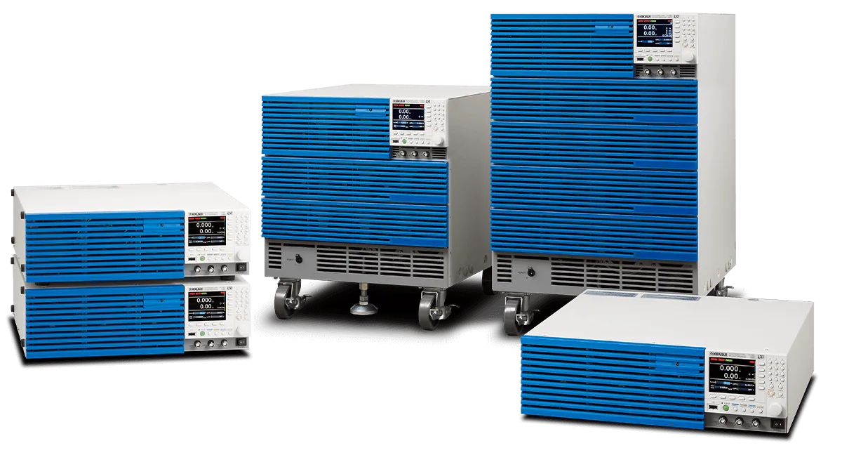
The PLZ-5WH2 high-power DC electronic load series is where durable, reliable ingenuity meets multifunctional, high-power design.Providing 5 variety of power range line-ups, from a 1 kW benchtop style model, to a high-power model that can sink up to 20 kW of power in a single unit.
You can easily select the applicable power range according to the load. Load simulation can be achieved faster than ever before thanks to the reliable, high-speed design of the PLZ-5WH2 current control circuits. Accurate current measures can be made with extremely high-setting resolution. A color LCD display allows for highly visible, user-friendly front-panel operation. RS232C, USB, and LAN digital inter faces are included as standard for simple integration into any system.
Compact High Voltage DC Electronic Load
Model:
PLZ-5WH2 Series
Maker:
KIKUSUI ELECTRONICS CORPORATION
Features
- Selectable operation modes
- Wide Ranging Operation Voltage up to 1000 V
- Maximum Slew Rate of 20 A/μs
- Up to 100 kW with parallel operation (Max. 5 units)
- LAN(LXI), USB and RS232C standard digital interface.
- Arbitrary I-V Characteristics (ARB) Mode
Line up
| Item | PLZ1005WH2 | PLZ2005WH2 | PLZ4005WH2 | PLZ12005WH2 | PLZ20005WH2 | |
|---|---|---|---|---|---|---|
| Operating voltage (DC) | 10 V to 1000 V | |||||
| Power | 1000 W | 2000 W | 4000 W | 12000 W | 20000 W | |
| Current | 20 A | 40 A | 80 A | 240 A | 400 A | |
| DC INPUT terminal’s isolation voltage | Positive pin: ±1000 V, Negative pin: ±900 V | |||||
| Minimum operating voltage | At the rated current | 10 V | ||||
| When the current begins to flow | 1.5 V or less | |||||
Video
Specifications
Rating
| Item | PLZ1005WH2 | PLZ2005WH2 | PLZ4005WH2 | PLZ12005WH2 | PLZ20005WH2 | |
|---|---|---|---|---|---|---|
| Operating voltage (DC) | 10 V to 1000 V | |||||
| Power | 1000 W | 2000 W | 4000 W | 12000 W | 20000 W | |
| Current | 20 A | 40 A | 80 A | 240 A | 400 A | |
| DC INPUT terminal’s isolation voltage | Positive pin: ±1000 V, Negative pin: ±900 V | |||||
| Minimum operating voltage | At the rated current | 10 V | ||||
| When the current begins to flow | 1.5 V or less | |||||
Constant current (CC) mode
| Item | PLZ1005WH2 | PLZ2005WH2 | PLZ4005WH2 | PLZ12005WH2 | PLZ20005WH2 | |
|---|---|---|---|---|---|---|
| Operating range | 0 A to 20 A | 0 A to 40 A | 0 A to 80 A | 0 A to 240 A | 0 A to 400 A | |
| Selectable range | 0.0000 A to 20.2000 A | 0.000 A to 40.400 A | 0.000 A to 80.800 A | 0.00 A to 242.40 A | 0.00 A to 404.00 A | |
| Resolution | 0.0005 A | 0.001 A | 0.002 A | 0.005 A | 0.01 A | |
| Setting accuracy | ±(0.2 % of setting + 0.1 % of rating) | |||||
| Parallel operation | ±(0.4 % of setting + 0.2 % of rating) | |||||
Constant resistance (CR) mode
| Item | PLZ1005WH2 | PLZ2005WH2 | PLZ4005WH2 | PLZ12005WH2 | PLZ20005WH2 | ||
|---|---|---|---|---|---|---|---|
| Operating range *1 | Range H | 500 mS to 0 S | 1 S to 0 S | 2 S to 0 S | 6 S to 0 S | 10 S to 0 S | |
| Range L | 5 mS to 0 S | 10 mS to 0 S | 20 mS to 0 S | 60 mS to 0 S | 100 mS to 0 S | ||
| Selectable range | Range H | 505.00 mS to 0.00 S | 1.01000 S to 0.00000 S | 2.02000 S to 0.00000 S | 6.0600 S to 0.00000 S | 10.1000 S to 0.0000 S | |
| Range L | 5.0500 mS to 0.0000 S | 10.1000 mS to 0.0000 S | 20.2000 mS to 0.000 S | 60.600 mS to 0.000 S | 101.000 mS to 0.000 S | ||
| Resolution | Range H | 0.01 mS | 0.00002 S | 0.00005 S | 0.0002 S | 0.0002 S | |
| Range L | 0.0001 mS | 0.0002 mS | 0.0005 mS | 0.002 mS | 0.002 mS | ||
| Setting accuracy*2 | Range H | ±(0.5 % of setting + 0.5 % of rating*3) | |||||
| Range L | ±(0.5 % of setting + 0.2 % of rating*3) | ||||||
| Parallel operation | Range H | ±(1.0 % of setting + 1.0 % of rating*3) | |||||
| Range L | ±(1.0 % of setting + 0.4 % of rating*3) | ||||||
| Response speed | NORM/FAST | ||||||
* 1. Conductance [S] = input current [A]/input voltage [V] = 1/resistance [Ω] * 2. Converted value at the input current. At the sensing point during remote sensing. * 3. Rated current
Constant voltage (CV) mode
| Item | PLZ1005WH2 | PLZ2005WH2 | PLZ4005WH2 | PLZ12005WH2 | PLZ20005WH2 | |
|---|---|---|---|---|---|---|
| Operating range | 10 V to 1000 V | |||||
| Selectable range | 0.00 V to 1010.00 V | |||||
| Resolution | 0.02 V | |||||
| Setting accuracy *1 | ±(0.05 % of setting + 0.05 % of rating) | |||||
| Parallel operation | ±(0.1 % of setting + 0.1 % of rating) | |||||
| Response speed | NORM/FAST | |||||
*1. With the input voltage within the operating range, and at the sensing point during remote sensing.
Constant power (CP) mode
| Item | PLZ1005WH2 | PLZ2005WH2 | PLZ4005WH2 | PLZ12005WH2 | PLZ20005WH2 | |
|---|---|---|---|---|---|---|
| Operating range | 0 W to 1000 W | 0 W to 2000 W | 0 W to 4000 W | 0 W to 12000 W | 0 W to 20000 W | |
| Selectable range | 0.00 W to 1010.00 W | 0.00 W to 2020.00 W | 0 W to 4040.00 W | 0.0000 kW to 12.1200 kW | 0.0000 kW to 20.2000 kW | |
| Resolution | 0.02 W | 0.05 W | 0.1 W | 0.0005 kW | ||
| Setting accuracy | ±(0.5 % of rating *1 + 0.02 A × Vin *2) | ±(0.5 % of rating *1 + 0.04 A × Vin *2) | ±(0.5 % of rating *1 + 0.08 A × Vin *2) | ±(0.5 % of rating *1 + 0.2 A × Vin *2) | ±(0.5 % of rating *1 + 0.4 A × Vin *2) | |
| Parallel operation | ±(1 % of power rating + 0.1 % current rating × Vin *2) | |||||
* 1. Rated power * 2. DC INPUT terminal voltage or SENSING terminal voltage.
Arbitrary I-V characteristics (ARB) mode
| Item | PLZ1005WH2 | PLZ2005WH2 | PLZ4005WH2 | PLZ12005WH2 | PLZ20005WH2 |
|---|---|---|---|---|---|
| Operating range | Three to 100 points of current values can be specified for the input voltage. Linear interpolation is applied between specified points. | ||||
| Response speed | 500 μs, 1 ms, 2 ms, 5 ms, 10 ms, 20 ms, 50 ms, 100 ms, or off | ||||
Measurement function
Voltmeter
| Item | PLZ1005WH2 | PLZ2005WH2 | PLZ4005WH2 | PLZ12005WH2 | PLZ20005WH2 | |
|---|---|---|---|---|---|---|
| Display | 0.00 V to 1000.00 V | |||||
| Resolution | 10 mV | |||||
| Accuracy | ±(0.05 % of reading + 0.05 % of rating) | |||||
| Parallel operation | ±(0.1 % of reading + 0.1 % of rating) (TYP) | |||||
Ammeter
| Item | PLZ1005WH2 | PLZ2005WH2 | PLZ4005WH2 | PLZ12005WH2 | PLZ20005WH2 | |
|---|---|---|---|---|---|---|
| Display | 0.000 A to 20.000 A | 0.000 A to 40.000 A | 0.000 A to 80.000 A | 0.00 A to 240.00 A | 0.00 A to 400.00 A | |
| Resolution | 0.001 A | 0.001 A | 0.001 A | 0.01 A | 0.01 A | |
| Accuracy | ±(0.2 % of reading + 0.1 % of rating) | |||||
| Parallel operation | ±(0.4 % of reading + 0.2 % of rating) (TYP) | |||||
Power display
| Item | PLZ1005WH2 | PLZ2005WH2 | PLZ4005WH2 | PLZ12005WH2 | PLZ20005WH2 |
|---|---|---|---|---|---|
| Display | Displays the product of the voltmeter reading and ammeter reading | ||||
Measurement trigger
| Item | PLZ1005WH2 | PLZ2005WH2 | PLZ4005WH2 | PLZ12005WH2 | PLZ20005WH2 |
|---|---|---|---|---|---|
| Trigger Source | Immediate, BUS, DIGITAL2, MSync, TALink, LoadOff | ||||
| Trigger Count | 1 to 65536 | ||||
| Trigger Delay | 0.00000 s to 100.00000 s | ||||
| Interval | Disable/Enable | ||||
| Interval Time | 0.00001 s to 3600 s | ||||
| Sense Aperture | 0.00001 s to 1.00000 s | ||||
Pulse function
| Item | PLZ1005WH2 | PLZ2005WH2 | PLZ4005WH2 | PLZ12005WH2 | PLZ20005WH2 | |
|---|---|---|---|---|---|---|
| Operation mode | CC and CR | |||||
| Frequency setting range | 1.0 Hz to 10.0 kHz | |||||
| Frequency setting resolution *1 | 1 Hz to 10 Hz | 0.1 Hz | ||||
| 11 Hz to 100 Hz | 1 Hz | |||||
| 110 Hz to 1000 Hz | 10 Hz | |||||
| 1.1 kHz to 10.0 kHz | 0.1 kHz | |||||
| Frequency setting accuracy | 1 Hz to 5.0 kHz | ±(0.5 % of setting) | ||||
| 5.1 Hz to 10.0 kHz | ±(1.0 % of setting) | |||||
| Duty cycle setting range, step | 1 Hz to 10 Hz | 5.0 % to 95.0 %, 0.1 % steps | ||||
| 11 Hz to 100 Hz | ||||||
| 110 Hz to 1000 Hz | ||||||
| 1.1 kHz to 10.0 kHz | 5 % to 95 % *2, 1 % steps | |||||
* 1. (Reference) The resolution actually set in the device is period resolution ⊿T = 1 μs, as shown in the equation below. For example, if you specify 9300 Hz, the period set in the device will be n × ⊿T = 108 × 1 μs = 108 μs (where “n” is a number set in the device). Converted to frequency, this becomes 1/108 μs = 9259 Hz. * 2. The minimum time span is 20 μs. The minimum duty cycle is limited by the minimum time span.
Switch value (Depth)
| Item *1 | PLZ1005WH2 | PLZ2005WH2 | PLZ4005WH2 | PLZ12005WH2 | PLZ20005WH2 | |
|---|---|---|---|---|---|---|
| CC mode | 0.0000 A to 20.2000 A | 0.000 A to 40.400 A | 0.000 A to 80.800 A | 0.000 A to 242.40 A | 0.00 A to 404.00 A | |
| CR mode | Range H | 505.00 mS to 0.00 S | 1010.00 mS to 0.00 S | 2020.00 mS to 0.00 S | 6.06000 S to 0.00000 S | 10.1000 S to 0.0000 S |
| Range L | 5.0500 mS to 0.0000 S | 10.1000 mS to 0.0000 S | 20.2000 mS to 0.0000 S | 60.600 mS to 0.000 S | 101.000 mS to 0.000 S | |
*1. The switch value is limited to the set current or set conductance or less.
Slew rate
| Item | PLZ1005WH2 | PLZ2005WH2 | PLZ4005WH2 | PLZ12005WH2 | PLZ20005WH2 |
|---|---|---|---|---|---|
| Operation mode | CC | ||||
| Operating range | 0.001 A/µs to 1 A/µs | 0.002 A/µs to 2 A/µs | 0.004 A/µs to 4 A/µs | 0.01 A/µs to 12 A/µs | 0.02 A/µs to 20 A/µs |
| Resolution | 0.00002 A/μs | 0.00005 A/μs | 0.0001 A/μs | 0.0002 A/μs | 0.0005 A/μs |
| Setting accuracy *1 | ±(10 % of setting + 20 μs) | ||||
*1. Time to change from 10 % to 90 % when the current is changed from 0 % to 100 % of the rated current
Sine Function
| Item | PLZ1005WH2 | PLZ2005WH2 | PLZ4005WH2 | PLZ12005WH2 | PLZ20005WH2 | |
|---|---|---|---|---|---|---|
| Operation mode | CC | |||||
| Frequency setting range | 1 Hz to 1000 Hz, 2000 Hz, 5000 Hz, 10000 Hz | |||||
| Frequency setting resolution *1 | 1 Hz to 10 Hz | 1 Hz | ||||
| 20 Hz to 100 Hz | 10 Hz100 Hz | |||||
| 200 Hz to 1000 Hz | ||||||
| 1000 Hz to | 2 kHz, 5 kHz, 10 kHz | |||||
| Frequency setting accuracy | 300 Hz to 900 Hz | ±(1.0 % of setting) | ||||
| Other than the frequencies above | ±(0.5 % of setting) | |||||
*1. (Reference) The resolution actually set in the device is period resolution ⊿T= 20 μs, as shown in the equation below. For example, if you specify 900 Hz, the period set in the device will be n × ⊿T = 56 × 20 μs = 1120 μs (where “n” is a number set in the device). Converted to frequency, this becomes 1/1120 μs ≈ 893 Hz.
Soft start
| Item | PLZ1005WH2 | PLZ2005WH2 | PLZ4005WH2 | PLZ12005WH2 | PLZ20005WH2 |
|---|---|---|---|---|---|
| Operation mode | CC | ||||
| Time setting range | 500 μs, 1 ms, 2 ms, 5 ms, 10 ms, 20 ms, 50 ms, 100 ms, or off | ||||
Alarm function
Alarm 1
| Item | PLZ1005WH2 | PLZ2005WH2 | PLZ4005WH2 | PLZ12005WH2 | PLZ20005WH2 |
|---|---|---|---|---|---|
| Overvoltage detection | Turns off the load when a voltage that is 110 % of the rating or higher is applied. | ||||
| Reverse-connection detection | Turns off the load when approximately -1 % of the rated current flows through the DC INPUT terminals. | ||||
| Overheat detection, overcurrent detection of the front-panel DC INPUT terminals | Turns off the load when the heatsink temperature reaches 100 °C. Or, turns off the load when a current of 30 A or higher is flowing through the front-panel DC INPUT terminals. | ||||
| Alarm input detection | Turns off the load when a voltage between 0 V and 1.5 V is applied to ALARM INPUT (pin 6) of the EXT CONT connector. | ||||
| Parallel operation anomaly detection | Turns off the load when any of the following errors occurs. • An error occurs in the communication between the master unit and slave unit during parallel operation. • slave unit’s power supply is interrupted. slave unit’s power supply is interrupted. • An overheating was detected on the master or slave unit. • An overcurrent flows through the front-panel DC INPUT terminals. • PLZ-5WH series or PLZ-5W series is connected as a slave. |
||||
Alarm 2
| Item | PLZ1005WH2 | PLZ2005WH2 | PLZ4005WH2 | PLZ12005WH2 | PLZ20005WH2 | |
|---|---|---|---|---|---|---|
| Overcurrent protection (OCP) |
Selectable range | 0.000 A to 22.000 A | 0.00 A to 44.00A | 0.00 A to 88.00A | 0.00 A to 264.00A | 0.00 A to 440.00A |
| Resolution | 0.001 A | 0.01 A | 0.01 A | 0.01 A | 0.1 A | |
| Protective operation | Select load off or limit. | |||||
| Overpower protection (OPP) |
Selectable range | 0.0 W to 1100.0 W | 0.0 W to 2200.00 W | 0 W to 4400 W | 0.000 W to 13.200 kW | 0.000 W to 22.000 kW |
| Resolution | 0.1 W | 0.1 W | 1 W | 0.001 kW | 0.001 kW | |
| Protective operation | Select load off or limit. | |||||
| Undervoltage protection (UVP) |
Selectable range | 0.00 V to 1000.00 V, or off. | ||||
| Resolution | 0.02 V | |||||
| Protective operation | Select load off or limit. | |||||
| Watchdog protection (WDP) |
Selectable range | 1 s to 3600 s or off | ||||
| Protective operation | Load off | |||||
Sequence function
| Item | PLZ1005WH2 | PLZ2005WH2 | PLZ4005WH2 | PLZ12005WH2 | PLZ20005WH2 |
|---|---|---|---|---|---|
| Operation mode | CC, CR, CV, CP | ||||
| Maximum number of programs | 30 | ||||
| Maximum number of steps | 10000 | ||||
| Step execution time | 0.000050 s to 3600000 s (50 µs to 1000 h) | ||||
| Time resolution | 1 μs | ||||
Integration display
| Item | PLZ1005WH2 | PLZ2005WH2 | PLZ4005WH2 | PLZ12005WH2 | PLZ20005WH2 | |
|---|---|---|---|---|---|---|
| Elapsed time display | Displays the time from load on to load off. | |||||
| Range | 0 s to 3600000 s (1000 h 0 min 0 s) | |||||
| Ampere-hour meter display | Displays integrated current | |||||
| Range | 0 Ah to 70000 Ah | 0 Ah to 140000 Ah | 0 Ah to 280000 Ah | 0 Ah to 800000 Ah | 0 Ah to 1400000 Ah | |
| Watt-hour meter display | Displays integrated power | |||||
| Range | 0 Wh to 40000000 Wh | 0 Wh to 80000000 Wh | 0 Wh to 160000000 Wh | 0 Wh to 500000000 Wh | 0 Wh to 800000000 Wh | |
Cutoff function
| Item | PLZ1005WH2 | PLZ2005WH2 | PLZ4005WH2 | PLZ12005WH2 | PLZ20005WH2 | |
|---|---|---|---|---|---|---|
| Elapsed time | The load turns off when the elapsed time value reaches the specified value. | |||||
| Range | 0 s to 3600000 s (1000 h 0 min 0 s) | |||||
| Resolution | 1 s | |||||
| Integrated current | The load turns off when the ampere-hour meter value reaches the specified value. | |||||
| Range | 0 Ah to 70000 Ah | 0 Ah to 140000 Ah | 0 Ah to 280000 Ah | 0 Ah to 800000 Ah | 0 Ah to 1400000 Ah | |
| Resolution | 0.001 mAh (0.000 mAh to 1000.000 mAh) 0.001 Ah (1.001 Ah to 1000.000 Ah) 0.001 kAh (1.001 kAh to 1 000.000 kAh) 0.001 MAh (1.001 MAh to 1.400 MAh) | |||||
| Integrated power | The load turns off when the watt-hour meter value reaches the specified value. | |||||
| Range | 0 Wh to 40000000 Wh | 0 Wh to 80000000 Wh | 0 Wh to 160000000 Wh | 0 Wh to 500000000 Wh | 0 Wh to 800000000 Wh | |
| Resolution | 0.001 Wh (0.000 Wh to 1 000.000 Wh) 0.001 kWh (1.001 kWh to 1 000.000 kWh) 0.001 MWh (1.001 MWh to 800.000 MWh) | |||||
| Voltage drop | The load turns off when the voltmeter value becomes less than or equal to the specified value. | |||||
| Range | 0.00 V to 1000.00 V | |||||
| Resolution | 0.02V | |||||
Other functions
| Item | PLZ1005WH2 | PLZ2005WH2 | PLZ4005WH2 | PLZ12005WH2 | PLZ20005WH2 | |
|---|---|---|---|---|---|---|
| Remote sensing | Input voltage rating *1 | 1000 V *2 | ||||
| Isolation voltage | ± 1000 V | |||||
| Number of units in parallel operation | 5 units | |||||
| Mutual synchronized operation *3 | Synchronizes load on/off. Synchronization of sequence execution, and sequence resumption. Synchronizing the recording timing of measured values. | |||||
* 1. There are limitations depending on the actual power that the load consumes. * 2. Total potential difference between the DC INPUT terminals and SENSING terminals * 3. The terminals for mutual synchronized operation are isolated from the DC INPUT terminals and operate at the chassis potential.
EXT CONT connector
| Item *1 |
PLZ1005WH2 | PLZ2005WH2 | PLZ4005WH2 | PLZ12005WH2 | PLZ20005WH2 | |
|---|---|---|---|---|---|---|
| Load on/off control input | Logic level switchable. Pulled up to 5 V by a 10 kΩ resistor. The thresholds are HIGH: 3.5 V to 5 V, LOW: 0 V to 1.5 V. | |||||
| Alarm input | An alarm is activated with a voltage between 0 V and 1.5 V. Pulled up to 5 V by a 10 kΩ resistor. The thresholds are HIGH: 3.5 V to 5 V, LOW: 0 V to 1.5 V. | |||||
| Alarm clearing input | After an alarm occurs, eliminate the root cause of the alarm, and change the input to pin 5 of the EXT CONT connector from a low level signal to a high level signal. The alarm will be cleared on the rising edge of this signal. Pulled up to 5 V by a 10 kΩ resistor. The thresholds are HIGH: 3.5 V to 5.0 V, LOW: 0 V to 1.5 V. | |||||
| Trigger input | Paused sequence operation resumes when a voltage between 0 V and 0.66 V is received. Pulled up to 5 V by a 10 kΩ resistor. The thresholds are HIGH: 2.31 V to 3.3 V, LOW: 0 V to 0.66 V. | |||||
| External voltage control input(CC, CR, CP mode) | Controls the load settings of CC, CR, CP mode through external voltage input. Input impedance: Approx. 10 kΩ. CC: The setting can be controlled in the range of 0 % to 100 % of the rated current through external voltage input of 0 V to 10 V. CR: The setting can be controlled in the range of 0 % to 100 % of the conductance setting through external voltage input of 0 V to 10 V. CP: The setting can be controlled in the range of 0 % to 100 % of the rated power through external voltage input of 0 V to 10 V. | |||||
| Setting accuracy | ±(1 % of rating) (TYP value in CC mode) | |||||
| External voltage control input (CV mode) | The load setting of CV mode can be controlled through external voltage input. The rated voltage can be controlled in the range of 0 % to 100 % with 0 V to 10 V. Input impedance: Approx. 10 kΩ. | |||||
| Setting accuracy | ±(1 % of rating) (TYP) | |||||
| External voltage control input (superimposing in CC mode) | Controls the load setting of CC mode by adding current through external voltage input. Adds current in the range of -100 % to 100 % of the rated current for -10 V to 10 V.Input impedance: Approx. 10 kΩ. | |||||
| Setting accuracy | ±(1 % of rating) (TYP) | |||||
| Load-on status output | On when load is on. Open-collector output from a photocoupler. *2 | |||||
| ALARM 1 output | ON when overvoltage detection, reverse-connection detection, overheat detection, front-panel DC INPUT overcurrent detection, alarm input detection, or parallel operation anomaly detection is activated. Open-collector output from a photocoupler. *2 | |||||
| ALARM 2 output | Turns on when OCP, OPP, UVP, or WDP is activated. Open-collector output from a photocoupler. *2 | |||||
| DIGITAL 0 output | Can be controlled through sequences. Output impedance: Approx. 330 Ω. The thresholds are HIGH: 2.5 V to 3.3 V, LOW: 0 V to 0.4 V. | |||||
| DIGITAL 1 output | ||||||
| DIGITAL 2 input/output | Input/output switchable. Output: Sequence trigger output. The output impedance is 330 Ω.The thresholds are HIGH: 2.5 V to 3.3 V, LOW: 0 V to 0.4 V. Input: Trigger input signal for the sequence and the measurement functions. The thresholds are HIGH: 2.31 V to 3.3 V, LOW: 0 V to 0.66 V | |||||
| Current monitor output | Outputs 0 V to 10 V for 0 % to 100 % of the rated current. Output impedance: 1 kΩ (TYP). | |||||
| Accuracy | ±(1 % of rating) (TYP) | |||||
* 1. 1000 V reinforced insulation between each terminal and the DC INPUT terminal * 2. The maximum voltage that can be applied to the photocoupler is 30 V. The maximum current is 4 mA.
BNC connector
| Item | PLZ1005WH2 | PLZ2005WH2 | PLZ4005WH2 | PLZ12005WH2 | PLZ20005WH2 | |
|---|---|---|---|---|---|---|
| Trigger output | Transmits 10 μs pulses during step execution when trigger output is set in a sequence. Transmits 10 μs pulses during pulse operation and sine operation. Output impedance: 200 Ω, output voltage HIGH: 4.2 V to 5.0 V, LOW: 0 V to 0.4 V. | |||||
| Current monitor output | Output voltage | Outputs 0 V to 10 V for 0 % to 100 % of the rated current | ||||
| Output impedance | 50 Ω (TYP) | |||||
| Accuracy | ±(1 % of rating) | |||||
| Voltage monitor output | Output voltage | Outputs the measured voltage with 1/100 magnification from 0 V to 10 V. | ||||
| Output impedance | 50 Ω (TYP) | |||||
| Accuracy | ±(1 % of rating) | |||||
| Isolation voltage | ± 30 V | |||||
Communication function
| Item | PLZ1005WH2 | PLZ2005WH2 | PLZ4005WH2 | PLZ12005WH2 | PLZ20005WH2 | |
|---|---|---|---|---|---|---|
| RS232C | Hardware | D-SUB 9-pin connector. Baud rate: 9600, 19200, 38400, 115200 bps. Data length: 8 bits, Stop bits: 1 bit, Parity bit: None Flow control: No, CTS/RTS | ||||
| Message terminator | LF during reception, LF during transmission. | |||||
| USB (device) | Hardware | Standard type B socket. Complies with the USB 2.0 specification. Data rate: 480 Mbps (High Speed). | ||||
| Message terminator | LF or EOM during reception, LF + EOM during transmission. | |||||
| Device class | Complies with the USBTMC-USB488 device class specifications | |||||
| USB (host) | Hardware | Standard type A socket Complies with the USB 2.0 specification. Data rate: 480 Mbps (High Speed). | ||||
| LAN | Hardware | IEEE 802,3 100Base-TX/10Base-T Ethernet IPv4, RJ-45 connector. | ||||
| Compliant standards | LXI 1.4 Core Specification 2011 | |||||
| Communication protocol | VXI-11, HiSLIP, SCPI-RAW, SCPI-Telnet | |||||
| Message terminator | VXI-11, HiSLIP: LF or END during reception, LF + END during transmission. SCPI-RAW: LF during reception, LF during transmission. | |||||
General Specifications
| Item | PLZ1005WH2 | PLZ2005WH2 | PLZ4005WH2 | PLZ12005WH2 | PLZ20005WH2 | |
|---|---|---|---|---|---|---|
| Input voltage range | 100 Vac to 240 Vac (90 Vac to 250 Vac) single phase | |||||
| Input frequency range | 47 Hz to 63 Hz | |||||
| Power consumption | 70 VAmax | 90 VAmax | 150 VAmax | 360 VAmax | 590 VAmax | |
| Inrush current (peak value) | 100 Vac | 30 Amax | 30 Amax | 30 Amax | 40 Amax | 40 Amax |
| 230 Vac | 80 Amax | 80 Amax | 80 Amax | 160 Amax | 160 Amax | |
| Leakage current*1 | 0.5 mA or less | 0.6 mA or less | 0.8 mA or less | 1.6 mA or less | 2.4 mA or less | |
| Environmental conditions | Operating temperature range | 0 °C to 40 °C (32 °F to 104 °F) | ||||
| Operating humidity range | 20 %rh to 85 %rh (no condensation) | |||||
| Storage temperature range | -25 °C to 60 °C (-13 °F to 140 °F) | |||||
| Storage humidity range | 90 %rh or less (no condensation) | |||||
| Installation location | Indoor use, altitude of up to 2000 m, overvoltage category II | |||||
| Insulation resistance | Between primary and chassis, input, monitor terminals | 1000 Vdc, 30 MΩ or more (70 %rh or less) | ||||
| Between input terminals and chassis, monitor terminal | 1000 Vdc, 3 MΩ or more (70 %rh or less) | |||||
| Withstanding voltage | Between primary and chassis, input, monitor terminals | No abnormalities at 1500 Vac for 2 s | ||||
| Between input terminals and chassis, monitor terminal | No abnormalities at 1500 Vac for 2 s | |||||
| Weight | Approx. 13 kg (28.66 lb) | Approx. 16 kg (35.3 lbs) | Approx. 20 kg (44.1 lbs) | Approx. 64 kg (141.1 lbs) | Approx. 93 kg (205 lbs) | |
| Accessories | [Common to all models] Power cord (1 pc., length: 2.5 m), Safety terminal adapter TL41 (red 1 set, black 1set), External control connector kit (1 set), Safety Information (1 copy), Setup Guide (1 copy), Quick Reference (Japanese 1 sheet, English 1 sheet), CD-ROM (1 disc) [PLZ1005WH2, PLZ2005WH2, PLZ4005WH2] Rear-panel DC INPUT terminal cover (1 set), Screw set for rear-panel DC INPUT terminals (2 sets), Screws for the rear-panel DC INPUT terminal cover (2 pcs.) , Front-panel DC INPUT terminal cover (1 pc.), Screws for the front-panel DC INPUT terminals (2 pcs.) , Heavy object warning label (1 pc.) PLZ4005WH2 only [PLZ12005WH2, PLZ20005WH2] Rear-panel DC INPUT terminals cover (1 set), Screw set for rear-panel DC INPUT terminals (2 sets), Rear-panel DC INPUT terminals cover screws (2 pcs.), Heavy object warning label (1 pc.), Parallel operation signal cable kit [PC02-PLZ-5W] |
|||||
| Electromagnetic compatibility (EMC) *2 *3 | Conforms to the requirements of the directive and standard below. EMC Directive 2014/30/EU EN 61326-1 (Class A *4), EN 55011 (Class A *4, Group 1 *5), EN 61000-3-2, EN 61000-3-3 Applicable under the following conditions The maximum length of all cabling and wiring connected to the product must be less than 3 m. |
|||||
| Safety *2 | Conforms to the requirements of the directive and standard below. EMC Directive 2014/35/EU *3 EN 61010-1 (Class I *6, Pollution Degree 2 *7) |
|||||
* 1. Leakage current between the positive and negative terminals of the rear-panel DC INPUT. At 1000 Vdc. * 2. Does not apply to specially ordered or modified products. * 3. Limited to models that have a CE mark on their panels. * 4. This is a Class A instrument. This product is intended for use in an industrial environment. This product may cause interference if used in residential areas. Such use must be avoided unless the user takes special measures to reduce electromagnetic emissions to prevent interference to the reception of radio and television broadcasts. * 5. This is a Group 1 instrument. This product does not generate and/or use intentionally radio-frequency energy, in the form of electromagnetic radiation, inductive and/or capacitive coupling, for the treatment of material or inspection/analysis purpose. * 6. This is a Class I instrument. Be sure to ground this product’s protective conductor terminal. The safety of this product is guaranteed only when the product is properly grounded. * 7. Pollution is addition of foreign matter (solid, liquid or gaseous) that may produce a reduction of dielectric strength or surface resistivity. Pollution Degree 2 assumes that only non-conductive pollution will occur except for an occasional temporary conductivity caused by condensation.