This website uses cookies so that we can provide you with the best user experience possible. Cookie information is stored in your browser and performs functions such as recognising you when you return to our website and helping our team to understand which sections of the website you find most interesting and useful.


ITEMLIST

- Products by Category
- KIKUSUI Electrical Safety Multi-analyzer TOS9300 Series
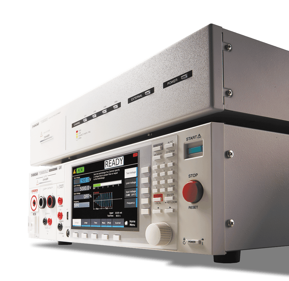
Hipot, Insulation Resistance, Ground Bond, Leakage or Partial Discharge, this analyzer covers it all!
The TOS9300 series is a high-performance electrical safety analyzer that complies with a wide range of universal standards. Hipot, Insulation Resistance, Ground Bond, Leakage Current (touch current and protective conductor current) and partial discharge can all be tested. A total of 6 models are available for standard compliance tests for a wide variety of applications including R&D, quality assurance manufacturing lines and laboratory tests.
Electrical Safety Multi-analyzer
Model:
TOS9300 Series
Maker:
KIKUSUI ELECTRONICS CORPORATION
Features
- All-in-one safety tester model (TOS9303LC)
Insulation diagnosis available with partial discharge model (TOS9301PD)
New amplifier type allows for 40 A AC/DC ground bond testing (Ground bond tester models) - Electrical breakdown inspection setting available
- AC5 kV/100 mA, DC7.2 kV/100 W Hipot test
- Touch current/protective conductor current/leakage current test (TOS9303LC)
- LAN/USB/RS232C standard digital interface
- Easy to read LCD display for real time monitoring during tests. All measurement values and standard outlines displayed in each test
- High voltage scanner capable of output distribution both standalone and when connected with existing withstanding voltage/insulation resistance testing equipment models [TOS5300 series, etc.] (TOS9320)
Video
Specifications
Withstanding Voltage Test
AC Output function
| AC output section | TOS9300 | TOS9301 | TOS9301PD | TOS9302 | TOS9303 | TOS9303LC | ||
|---|---|---|---|---|---|---|---|---|
| AC output section | Output range | 0.050 kV to 5.000 kV | ||||||
| Resolution | 1 V | |||||||
| Setting accuracy | ±(1.2 % of setting + 0.02 kV) (at no load) | |||||||
| Max. rated load *1 | 500 VA(5 kV / 100 mA) | |||||||
| Max. rated current | 100 mA (when the output voltage is 0.2 kV or higher) | |||||||
| Transformer rating | 500 VA | |||||||
| Output voltage waveform *2 | Sine | |||||||
| Distortion | 2 % or less. (when the output voltage is 0.5 kV or higher and no load or a pure resistive load is connected) | |||||||
| Crest factor | √2 ± 3 % (0.8 kV or higher) | |||||||
| Frequency | 50 Hz / 60 Hz | |||||||
| Accuracy | ±0.1 % | |||||||
| Voltage regulation | ±3 % or less (when changing from maximum rated load to no load) | |||||||
| Short-circuit current | 200 mA or more (output voltage 0.5 kV or higher) | |||||||
| Output method | PWM switching | |||||||
| Start voltage | The voltage at the start of the test can be set. | |||||||
| Setting range | 1 % to 99 % of the test voltage | |||||||
| Resolution | 1% | |||||||
| Output voltage monitor function | If the output voltage exceeds ±(10 % of setting + 0.05 kV), the output is turned off, and the protection function is activated. | |||||||
DC Output function
| AC output section | TOS9301 | TOS9301PD | TOS9303 | TOS9303LC | ||
|---|---|---|---|---|---|---|
| DC output section | Output range | 0.050 kV to 7.200 kV | ||||
| Resolution | 1 V | |||||
| Setting accuracy | ±(1.2 % of setting + 0.02 kV) | |||||
| Max. rated load *1 | 100 W (5 kV/20 mA, 7.2 kV/13.9 mA) | |||||
| Max. rated current | 20 mA | |||||
| Ripple | 7.2 kV no load | 20 Vp-p (TYP) | ||||
| Max. rated load | 50 Vp-p (TYP) | |||||
| Voltage regulation | 1 % or less (when changing from maximum rated load to no load) | |||||
| Short-circuit current | 100 mA (TYP) (200 mA peak) | |||||
| Discharge function | Forced discharge after test completion (discharge resistance: 125 kΩ) | |||||
| Start voltage | The voltage at the start of the test can be set. | |||||
| Setting range | 1 % to 99 % of the test voltage | |||||
| Resolution | 1% | |||||
| Output voltage monitor function | If the output voltage exceeds ±(10 % of setting + 0.05 kV), the output is turned off, and the protection function is activated. | |||||
*1 When tests are performed consecutively, output time limit and rest time may become necessary depending on the upper limit setting *2 If an AC voltage is applied to a capacitive load, the output voltage may rise higher than at no load depending on the load capacitance. Further, waveform distortions may occur if an EUT whose capacitance is dependent on voltage (for example, an EUT that consists of ceramic capacitors) is connected as the load. However, if the test voltage is 1.5 kV, the effect of a capacitance of 1 000 pF or less can be ignored. Because the product’s high-voltage power supply uses the PWM switching method, if the test voltage is 500 V or less, the switching and spike noise proportions are large. The lower the test voltage, the greater the waveform is distorted.
Measurement function
| Item | TOS9300 | TOS9301 | TOS9301PD | TOS9302 | TOS9303 | TOS9303LC | |
|---|---|---|---|---|---|---|---|
| Voltmeter | Measurement range | 0.00 kV to 7.50 kV AC/DC | |||||
| Resolution | 0.1 V | ||||||
| Accuracy | ±(1.2 % of reading + 0.005 kV) | ||||||
| Response | Can be switched between true rms and mean-value response rms conversion. | ||||||
| Peak-value response in a separate system (the peak-value response is for measuring the dielectric breakdown voltage while rising) | |||||||
| Hold function | The voltage measurement after a test is finished is held while the pass/fail judgment is displayed. | ||||||
| Ammeter *1 *2 | Measurement range | AC: 0.00 mA to 110 mA, DC: 0.00 mA to 22 mA (Current including the active component and reactive component) | |||||
| Accuracy | ±(1 % of reading + 2 μA) (active component) | ||||||
| Response | Can be switched between true rms and mean-value response rms conversion. | ||||||
| Hold function | The current measurement after a test is finished is held while the pass judgment is displayed. | ||||||
| Offset cancel function | Cancels up to 10 mA of the current flowing through the insulation resistance and stray capacitance components across output cables and the like (resistance component only for DC tests). OFF function available. | ||||||
| Calibration | Active component: Calibrated with the rms of a sine wave using a pure resistive load. Reactive component: Not calibrated. | ||||||
*1 During AC voltage tests, current also flows in the stray capacitance of items such as the test leads and tools. For details on stray capacitance, see “Stray Capacitance of AC Withstanding Voltage Tests” *2 When the temperature and humidity are high, erroneous current from the product’s internal and external high-voltage wiring sections to ground increases. When the humidity exceeds 70 %, an erroneous current of about 50 μA may be generated.
Judgment feature
| Item | TOS9300 | TOS9301 | TOS9301PD | TOS9302 | TOS9303 | TOS9303LC | ||
|---|---|---|---|---|---|---|---|---|
| Current judgment operation | The output is shut off when a judgment is made. Buzzer volume level can be set in the range of 0 (OFF) to 10 for pass and fail separately. In an auto test, the buzzer is valid only for the judgment that takes place at the end of the program. | |||||||
| UPPER FAIL | Judgment method | UPPER FAIL results when a current greater than or equal to the Upper limit is detected. For DCW, judgment is not made during the judgment delay (Judge Delay). | ||||||
| Display | “U-FAIL” is displayed. | |||||||
| Buzzer | On | |||||||
| SIGNAL I/O | The Upper-FAIL signal is generated continuously until a STOP signal is received. | |||||||
| Lower FAIL | Judgment method | LOWER FAIL results when a current less than or equal to the Lower limit is detected. Judgment is not made during Voltage rise time or Voltage fall time of an ACW test. | ||||||
| Display | “L-FAIL” is displayed. | |||||||
| Buzzer | On | |||||||
| SIGNAL I/O | The Lower-FAIL signal is generated continuously until a STOP signal is received. | |||||||
| PASS | Judgment method | PASS judgment is made if U-FAIL or L-FAIL has not occurred when the test time elapses. | ||||||
| Display | “PASS” is displayed. | |||||||
| Buzzer | On (fixed to 50 ms) | |||||||
| SIGNAL I/O | The PASS signal is generated for the length of time specified by the Pass Hold set-ting. If Pass Hold is set to Infinity, the PASS signal is generated continuously until a STOP signal is received. | |||||||
| Voltage rise rate judgment operation | Monitors the voltage rise rate during Voltage rise time. This is valid when Auto setting of the judgment delay (Delay Auto) is set to on and the output voltage is 200 V or more. The output is shut off when a judgment is made. Buzzer volume level can be set in the range of 0 (OFF) to 10 for pass and fail separately. | |||||||
| dV/dt FAIL | Judgment method | When the voltage rise rate (dV/dt) is less than approx. 1 V/s. | ||||||
| Display | “ Upper-FAIL(dv/dt)” is displayed. | |||||||
| Buzzer | On | |||||||
| SIGNAL I/O | The U-FAIL signal is generated continuously until a STOP signal is received. | |||||||
| Upper limit setting range | AC: 0.01 mA to 110.00 mA, DC: 0.01 mA to 21.00 mA | |||||||
| Lower limit setting range | AC: 0.00 mA to 109.99 mA, DC: 0.00 mA to 20.99 mA, OFF. Setting 0.00 is equivalent to OFF. | |||||||
| Judgment accuracy *1 *2 | ±(1 % of setting + 5 μA) | |||||||
| Current detection method | Compares to the reference value using the following method. Calculate true rms values, convert mean-value responses to rms values | |||||||
| Response speed (filter) switching | Switches the current detection response speed (sensitivity) used in UPPER FAIL judgment between five levels in ACW and DCW tests. | |||||||
*1 During AC voltage tests, current also flows in the stray capacitance of items such as the test leads and tools. For details on stray capacitance, see “Stray Capacitance of AC Withstanding Voltage Tests” *2 When the temperature and humidity are high, erroneous current from the product’s internal and external high-voltage wiring sections to ground increases. When the humidity exceeds 70 %, an erroneous current of about 50 μA may be generated.
Timer function
| AC output section | TOS9300 | TOS9301 | TOS9301PD | TOS9302 | TOS9303 | TOS9303LC |
|---|---|---|---|---|---|---|
| Current rise time settings range | 0.1 s to 200.0 s | |||||
| Current fall time setting time *1 | 0.1 s to 200.0 s, OFF | |||||
| Test time setting range | 0.1 s to 1000.0 s, OFF | |||||
| Judgment delay (Judge Delay) setting range *2 | 0.1 s to 100.0 s, AUTO *3 (DCW only) | |||||
| Accuracy | ±(100 ppm of setting + 20 ms) (excluding the fall time) | |||||
*1 This setting is used only when a PASS judgment occurs in ACW and DCW tests. During a DCW test, the voltage may not drop all the way within the set time because of the electrostatic capacity inside the product and the EUT. *2 Less than the sum of the rise time and fall time. *3 If Delay Auto is set to on, LOWER judgment is not made until the charge time ends.
Other specifications
| AC output section | TOS9300 | TOS9301 | TOS9301PD | TOS9302 | TOS9303 | TOS9303LC | |
|---|---|---|---|---|---|---|---|
| Analog monitor *1 | Outputs a voltage signal according to the current waveform or voltage waveform | ||||||
| I | Current waveform: Scale 50 mA/1 V | ||||||
| V | Voltage waveform: Scale 1 kV/1 V | ||||||
| Grounding mode (GND) | Can be switched between Low and Guard. | ||||||
| Low | GND is connected to the low terminal. Measures the current flowing across the low terminal and chassis (normal applications). | ||||||
| Guard *2 | GND is connected to Guard. Measures only the current flowing through the low terminal (cur-rent flowing through the chassis is not measured) (high sensitivity, high accuracy measure-ment applications). | ||||||
*1 Monitor signal output is isolated from the chassis (earth). If you connect an oscilloscope or an external device whose BNC shield is grounded, be sure to set the grounding mode (GND) to Guard. The value is not calibrated. *2 If there is a possibility that the EUT or tools and the like will be grounded or if you are uncertain, do not set GND to Guard. Doing so is extremely dangerous because the ammeter will be shorted and will not be able to measure current. For normal applications, set GND to Low.
Insulation Resistance Test
Output function
| Item | TOS9300 | TOS9301 | TOS9301PD | TOS9303 | TOS9303LC | ||
|---|---|---|---|---|---|---|---|
| Negative polarity | Output voltage range | -0.025 kV to -1 kV | |||||
| Resolution | 1 V | ||||||
| Setting accuracy | ±(1.2 % of setting + 0.002 kV) | ||||||
| Max. rated load | 1 W (-1 kV/1 mA) | ||||||
| Ripple | 1 kV no load | 2 Vp-p or less | |||||
| Max. rated load | 10 Vp-p or less | ||||||
| Short-circuit current | 12 mA or less | ||||||
| Positive polarity *1 | Output voltage range | – | +0.05 kV to +7.2 kV | ||||
| Resolution | 1 V | ||||||
| Setting accuracy | ±(1.2 % of setting + 0.02 kV) | ||||||
| Max. rated load | 7.2 W(7.2 kV/1 mA) | ||||||
| Ripple | 1 kV no load | 20 Vp-p or less | |||||
| Max. rated load | 50 Vp-p or less | ||||||
| Short-circuit current | 100 mA (TYP) (200 mA peak) | ||||||
| Max. rated current | 1 mA | ||||||
| Voltage regulation | 1 % or less (when changing from maximum rated load to no load) | ||||||
| Discharge function | Forced discharge after test completion (discharge resistance: 20 kΩ) | ||||||
| Output voltage monitor function | If the output voltage exceeds ±(10 % of setting + 0.05 kV), the output is turned off, and the protection function is activated. | ||||||
*1 TOS9300 are not supported.
Measurement function
| Item | TOS9300 | TOS9301 | TOS9301PD | TOS9303 | TOS9303LC | ||
|---|---|---|---|---|---|---|---|
| Voltmeter | Measurement range | Negative polarity: 0 Vdc to -1200 Vdc, positive polarity: 0 Vdc to 7500 Vdc | |||||
| Resolution | 0.1 V | ||||||
| Accuracy | Negative polarity: ±(1 % of reading + 1 V), positive polarity: ±(1.2 % of reading + 1 V) | ||||||
| Resistance meter | Measurement range | 0.001 MΩ to 100.0 GΩ (in the range of maximum rated current of 1 mA to 5 nA) | |||||
| Accuracy *1 *2 (when GND is set to Guard) (i: measured current)(R: measurement resistance) | 5 nA ≤ i ≤ 50 nA *3 | 500.000 MΩ ≤ R < 1.000 GΩ: ±(15 % of reading + 0.5 MΩ) 1.000 GΩ ≤ R < 10.000 GΩ: ±(15 % of reading + 5 MΩ) 10.000 GΩ ≤ R ≤ 100.000 GΩ: ±(20 % of reading + 200 MΩ) |
|||||
| 50 nA < i ≤ 100 nA *3 | 200.000 MΩ ≤ R < 1.000 GΩ: ±(10 % of reading + 0.5 MΩ) 1.000 GΩ ≤ R < 10.000 GΩ: ±(10 % of reading + 5 MΩ) 10.000 GΩ ≤ R < 50.000 GΩ: ±(10 % of reading + 50 MΩ) 50.000 GΩ ≤ R ≤ 100.000 GΩ: ±(20 % of reading + 200 MΩ) |
||||||
| 100 nA < i ≤ 200 nA *4 | 100.000 MΩ ≤ R < 1.000 GΩ: ±(7 % of reading + 0.5 MΩ) 1.000 GΩ ≤ R < 2.000 GΩ: ±(7 % of reading + 5 MΩ) 2.000 GΩ ≤ R < 10.000 GΩ: ±(7 % of reading + 10 MΩ) 10.000 GΩ ≤ R < 50.000 GΩ: ±(7 % of reading + 100 MΩ) |
||||||
| 200 nA < i ≤ 1 μA *4 | 10.000 MΩ≤ R < 100.000 MΩ: ±(5 % of reading + 0.05 MΩ) 100.000 MΩ ≤ R < 1.000 GΩ: ±(5 % of reading + 0.5 MΩ) 1.000 GΩ ≤ R < 10.000 GΩ: ±(5 % of reading + 5 MΩ) 10.000 GΩ ≤ R < 25.000 GΩ: ±(5 % of reading + 50 MΩ) |
||||||
| 1 μA < i ≤ 1 mA *4 | 0.001 MΩ ≤ R < 10.000 MΩ: ±(2 % of reading + 0.003 MΩ) 10.000 MΩ ≤ R < 100.000 MΩ: ±(2 % of reading + 0.03 MΩ) 100.000 MΩ ≤ R < 1.000 GΩ: ±(2 % of reading + 0.3 MΩ) 1.000 GΩ ≤ R < 5.000 GΩ: ±(2 % of reading + 3 MΩ) |
||||||
| Accuracy *5 (when GND is set to Low)(i: measured current)(R: measurement resistance) | 5 nA ≤ i ≤ 50 nA *3 | 500.000 MΩ≤ R < 1.000 GΩ: ±(25 % of reading + 0.5 MΩ) 1.000 GΩ≤ R < 10.000 GΩ: ±(25 % of reading + 5 MΩ) 10.000 GΩ≤ R ≤ 100.000 GΩ: ±(30 % of reading + 200 MΩ) |
|||||
| 50 nA < i ≤ 100 nA *3 | 200.000 MΩ≤ R < 1.000 GΩ: ±(20 % of reading + 0.5 MΩ) 1.000 GΩ≤ R < 10.000 GΩ: ±(20 % of reading + 5 MΩ) 10.000 GΩ≤ R < 50.000 GΩ: ±(20 % of reading + 50 MΩ) 50.000 GΩ≤ R ≤ 100.000 GΩ: ±(30 % of reading + 200 MΩ) |
||||||
| 100 nA < i ≤ 200 nA *4 | 100.000 MΩ≤ R < 1.000 GΩ: ±(10 % of reading + 0.5 MΩ) 1.000 GΩ≤ R < 2.000 GΩ: ±(10 % of reading + 5 MΩ) 2.000 GΩ≤ R < 10.000 GΩ: ±(10 % of reading + 10 MΩ) 10.000 GΩ≤ R < 50.000 GΩ: ±(10 % of reading + 100 MΩ) |
||||||
| 200 nA < i ≤ 1 μA *4 | 10.000 MΩ≤ R < 100.000 MΩ: ±(5 % of reading + 0.05 MΩ) 100.000 MΩ≤ R < 1.000 GΩ: ±(5 % of reading + 0.5 MΩ) 1.000 GΩ≤ R < 10.000 GΩ: ±(5 % of reading + 5 MΩ) 10.000 GΩ≤ R < 25.000 GΩ: ±(5 % of reading + 50 MΩ) |
||||||
| 1 μA < i ≤ 1 mA *3 | 0.001 MΩ≤ R < 10.000 MΩ: ±(2 % of reading + 0.003 MΩ) 10.000 MΩ≤ R < 100.000 MΩ: ±(2 % of reading + 0.03 MΩ) 100.000 MΩ≤ R < 1.000 GΩ: ±(2 % of reading + 0.3 MΩ) 1.000 GΩ≤ R < 5.000 GΩ: ±(2 % of reading + 3 MΩ) |
||||||
| Hold function | The resistance measurement after a test is finished is held while the pass judgment is displayed. | ||||||
| Offset cancel function | Cancels up to 2000 GΩ of the unnecessary insulation resistance across output cables and the like. OFF function available. | ||||||
*1 Humidity: 70 %rh or less (no condensation), when there is no interference caused by wobbly test leads or other problems. *2 If the grounding mode (GND) is set to low in a highly humid environment, leakage current to ground will be generated from the high-voltage wiring sections inside the product and the high-voltage wiring sections between the product and the EUT. This leakage current ranges from several nA to several tens of nA depending on the usage and wiring conditions of the optional TOS9320 high voltage scanner and greatly affects measurement accuracy. The effects of leakage current can be reduced by making measurements with the offset enabled. *3 Add 10 % to the accuracy when measuring 100 V or less. *4 Add 5 % to the accuracy when measuring 100 V or less. *5 When the measured current is limited to 100 nA or more (no condensation) when the humidity is 50 %rh or less, no external disturbance is present such as swinging test leads, and the offset is enabled.
Judgment feature
| Item | TOS9300 | TOS9301 | TOS9301PD | TOS9303 | TOS9303LC | ||
|---|---|---|---|---|---|---|---|
| Behavior based on judgment | The output is shut off when a judgment is made. Buzzer volume level can be set in the range of 0 (OFF) to 10 for pass and fail separately. In an auto test, the buzzer is valid only for the judgment that takes place at the end of the program. | ||||||
| UPPER FAIL | Judgment method | AC Output function||||||
| Buzzer | On | ||||||
| SIGNAL I/O | The Upper-FAIL signal is generated continuously until a STOP signal is received. | ||||||
| Lower FAIL | Judgment method | LOWER FAIL results when a resistance less than or equal to the Lower limit is detected. Judgment is not made during the judgment delay (Judge Delay). | |||||
| Display | “L-FAIL” is displayed. | ||||||
| Buzzer | On | ||||||
| SIGNAL I/O | The Lower-FAIL signal is generated continuously until a STOP signal is received. | ||||||
| PASS | Judgment method | PASS judgment is made if U-FAIL or L-FAIL has not occurred when the test time elapses. | |||||
| Display | “PASS” is displayed. | ||||||
| Buzzer | On (fixed to 50 ms) | ||||||
| SIGNAL I/O | The PASS signal is generated for the length of time specified by the Pass Hold setting. If Pass Hold is set to Infinity, the PASS signal is generated continuously until a STOP signal is received. | ||||||
| Voltage rise rate judgment operation | Monitors the voltage rise rate during Voltage rise time. This is valid when Auto setting of the judgment delay (Delay Auto) is set to on and the output voltage is 200 V or more. The output is shut off when a judgment is made. Buzzer volume level can be set in the range of 0 (OFF) to 10 for pass and fail separately. | ||||||
| dV/dt FAIL | Judgment method | When the voltage rise rate (dV/dt) is less than 1 V/s. | |||||
| Display | “ Lower-FAIL(dv/dt)” is displayed. | ||||||
| Buzzer | On | ||||||
| SIGNAL I/O | The L FAIL signals are generated continuously until a STOP signal is received. | ||||||
| Upper limit setting range | 0.001 MΩ to 100.000 GΩ (in the range up to the maximum rated current), OFF | ||||||
| Lower limit setting range | 0.000 MΩ to 99.999 GΩ (in the range up to the maximum rated current), OFF. Setting 0.000 is equivalent to OFF. | ||||||
| Accuracy *1 *2 *3 (when GND is set to Guard) (i: measured current) (R: measurement resistance) | 5 nA ≤ i ≤ 50 nA *4 | 500.000 MΩ ≤ R < 1.000 GΩ : ±(15 % of setting + 0.51 MΩ) 1.000 GΩ ≤ R < 10.000 GΩ : ±(15 % of setting + 15 MΩ) 10.000 GΩ ≤ R ≤ 100.000 GΩ : ±(20 % of setting + 210 MΩ) |
|||||
| 50 nA < i ≤ 100 nA *4 | 200.000 MΩ ≤ R < 1.000 GΩ : ±(10 % of setting + 0.51 MΩ) 1.000 GΩ ≤ R < 10.000 GΩ : ±(10 % of setting + 15 MΩ) 10.000 GΩ ≤ R < 50.000 GΩ : ±(10 % of setting + 60 MΩ) 50.000 GΩ ≤ R ≤ 100.000 GΩ : ±(20 % of setting + 210 MΩ) |
||||||
| 100 nA < i ≤ 200 nA *5 | 100.000 MΩ ≤ R < 1.000 GΩ : ±(7 % of setting + 0.51 MΩ) 1.000 GΩ ≤ R < 2.000 GΩ : ±(7 % of setting + 15 MΩ) 2.000 GΩ ≤ R < 10.000 GΩ : ±(7 % of setting + 20 MΩ) 10.000 GΩ ≤ R < 50.000 GΩ : ±(7 % of setting + 110 MΩ) |
||||||
| 200 nA < i ≤ 1 μA *5 | 10.000 MΩ ≤ R < 100.000 MΩ : ±(5 % of setting + 0.06 MΩ) 100.000 MΩ ≤ R < 1.000 GΩ : ±(5 % of setting + 0.51 MΩ) 1.000 GΩ ≤ R < 10.000 GΩ : ±(5 % of setting + 15 MΩ) 10.000 GΩ ≤ R < 25.000 GΩ : ±(5 % of setting + 60 MΩ) |
||||||
| 1 μA < i ≤ 1 mA *5 | 0.001 MΩ ≤ R < 10.000 MΩ : ±(2 % of setting + 0.013 MΩ) 10.000 MΩ ≤ R < 100.000 MΩ : ±(2 % of setting + 0.04 MΩ) 100.000 MΩ ≤ R < 1.000 GΩ : ±(2 % of setting + 0.31 MΩ) 1.000 GΩ ≤ R < 5.000 GΩ : ±(2 % of setting + 13 MΩ) |
||||||
| Accuracy *6 (when GND is set to Low) (i: measured current) (R: measurement resistance) | 5 nA ≤ i ≤ 50 nA *4 | 500.000 MΩ ≤ R < 1.000 GΩ : ±(25 % of setting + 0.51 MΩ) 1.000 GΩ ≤ R < 10.000 GΩ : ±(25 % of setting + 15 MΩ) 10.000 GΩ ≤ R ≤ 100.000 GΩ : ±(30 % of setting + 210 MΩ) |
|||||
| 50 nA < i ≤ 100 nA *4 | 200.000 MΩ ≤ R < 1.000 GΩ : ±(20 % of setting + 0.51 MΩ) 1.000 GΩ ≤ R < 10.000 GΩ : ±(20 % of setting + 15 MΩ) 10.000 GΩ ≤ R < 50.000 GΩ : ±(20 % of setting + 60 MΩ) 50.000 GΩ ≤ R ≤ 100.000 GΩ : ±(30 % of setting + 210 MΩ) |
||||||
| 100 nA < i ≤ 200 nA *5 | 100.000 MΩ ≤ R < 1.000 GΩ : ±(10 % of setting + 0.51 MΩ) 1.000 GΩ ≤ R < 2.000 GΩ : ±(10 % of setting + 15 MΩ) 2.000 GΩ ≤ R < 10.000 GΩ : ±(10 % of setting + 20 MΩ 10.000 GΩ ≤ R < 50.000 GΩ : ±(10 % of setting + 110 MΩ) |
||||||
| 200 nA < i ≤ 1 μA *5 | 10.000 MΩ ≤ R < 100.000 MΩ : ±(5 % of setting + 0.06 MΩ) 100.000 MΩ ≤ R < 1.000 GΩ : ±(5 % of setting + 0.51 MΩ) 1.000 GΩ ≤ R < 10.000 GΩ : ±(5 % of setting + 15 MΩ) 10.000 GΩ ≤ R < 25.000 GΩ : ±(5 % of setting + 60 MΩ) |
||||||
| 1 μA < i ≤ 1 mA *5 | 0.001 MΩ ≤ R < 10.000 MΩ : ±(2 % of setting + 0.013 MΩ) 10.000 MΩ ≤ R < 100.000 MΩ : ±(2 % of setting + 0.04 MΩ) 100.000 MΩ ≤ R < 1.000 GΩ : ±(2 % of setting + 0.31 MΩ) 1.000 GΩ ≤ R < 5.000 GΩ : ±(2 % of setting + 13 MΩ) |
||||||
*1 Making judgments on 200 μA or less requires at least 3 seconds after the rise time ends. Making judgments when the low pass filter is set to on requires at least 10 seconds after the rise time ends. *2 Humidity: 70 %rh or less (no condensation), when there is no interference caused by wobbly test leads or other problems. *3 If the grounding mode (GND) is set to low in a highly humid environment, leakage current to ground will be generated from the high-voltage wiring sections inside the product and the high-voltage wiring sections between the product and the EUT. This leakage current ranges from several nA to several tens of nA depending on the usage and wiring conditions of the optional TOS9320 high voltage scanner and greatly affects measurement accuracy. The effects of leakage current can be reduced by making measurements with the offset enabled. *4 Add 10 % to the accuracy when measuring 100 V or less. *5 Add 5 % to the accuracy when measuring 100 V or less. *6 When the measured current is limited to 100 nA or more (no condensation) when the humidity is 50 %rh or less, no external disturbance is present such as swinging test leads, and the offset is enabled.
Timer function
| Item | TOS9300 | TOS9301 | TOS9301PD | TOS9303 | TOS9303LC |
|---|---|---|---|---|---|
| Current rise time settings range | 0.1 s to 200.0 s | ||||
| Test time setting range | 0.1 s to 1000.0 s, OFF | ||||
| Judgment delay (Judge Delay) setting range *1 | 0.1 s to 100.0 s, AUTO *2 | ||||
| Accuracy *3 | ±(100 ppm of setting + 20 ms) | ||||
*1 Less than the sum of the rise time and fall time. *2 If Delay Auto is set to on, UPPER judgment is not made until the charge time ends. *3 This excludes fall time.
Other specifications
| Item | TOS9300 | TOS9301 | TOS9301PD | TOS9303 | TOS9303LC | |
|---|---|---|---|---|---|---|
| Grounding mode (GND) | Can be switched between Low and Guard. | |||||
| Low | GND is connected to the low terminal. Measures the current flowing across the low terminal and chassis (normal applications). | |||||
| Guard *1 | GND is connected to Guard. Measures only the current flowing through the low terminal (current flowing through the chassis is not measured) (high sensitivity, high accuracy measurement applications). | |||||
| Filter function | A low-pass filter can be inserted into the ammeter measurement circuit. *2 | |||||
*1 If there is a possibility that the EUT or tools and the like will be grounded or if you are uncertain, do not set GND to Guard. Doing so is extremely dangerous because the ammeter will be shorted and will not be able to measure current. For normal applications, set GND to Low. *2 When the low pass filter is on, a judgment delay of at least 5 seconds and a test time are required.
Earth Continuity Test
Output function
| Item | TOS9302 | TOS9303 | TOS9303LC | ||
|---|---|---|---|---|---|
| Current setting range *1 | 3.0 A to 42.0 A AC/DC | ||||
| Resolution | 0.1 A | ||||
| Accuracy | ±(1 % of setting + 0.4 A) | ||||
| AC | Maximum rated output *2 | 220 VA (at the output terminal) | |||
| Distortion | 2 % or less (20 A or more, using a 0.1 Ω pure resistive load) | ||||
| Frequency | Select 50 Hz or 60 Hz. Sine | ||||
| Accuracy | ±200 ppm | ||||
| Open terminal voltage | 6 Vrms or less | ||||
| Output method | PWM switching | ||||
| DC | Maximum rated output | 220 W (at the output terminal) | |||
| Ripple | ±0.4 Ap-p or less (TYP) | ||||
| Open terminal voltage | 6.0 V or less | ||||
*1 No greater than the maximum rated output and resistance no greater than the output terminal voltage 5.4 V. *2 When tests are performed consecutively, output time limit and rest time may become necessary depending on the upper limit setting.
Measurement function
| Item | TOS9302 | TOS9303 | TOS9303LC | |
|---|---|---|---|---|
| Output ammeter | Measurement range | 0.0 A to 45.0 A AC/DC | ||
| Resolution | 0.01 A | |||
| Accuracy | ±(1 % of reading + 0.2 A) | |||
| Response | AC: RMS value display of average value response, DC: mean value | |||
| Hold function | The current measurement after a test is finished is held while the pass or fail judgment is displayed. | |||
| Output voltmeter | Measurement range | AC: 0.00 V to 6.00 V, DC: 0.00 V to 5.50 V | ||
| Resolution | 0.001 V | |||
| Offset cancel function | Cancels up to 5 V (AC/DC) of the unnecessary voltage from measurements. OFF function available. | |||
| Accuracy | ±(1 % of setting + 0.02 V) | |||
| Response | AC: RMS value display of average value response, DC: mean value | |||
| Hold function | The voltage measurement after a test is finished is held while the pass or fail judgment is displayed. | |||
| Resistance meter | Measurement range *1 | 1 mΩ to 600 mΩ | ||
| Resolution | 1 mΩ | |||
| Offset cancel function | Cancels up to 10 Ω of the unnecessary resistance from measurements. OFF function available. | |||
| Accuracy | ±(2 % of reading + 3 mΩ) | |||
| Hold function | The resistance measurement after a test is finished is held while the pass judgment is displayed. | |||
*1 Calculated from the measured output voltage and measured output current.
Judgment feature
| Item | TOS9302 | TOS9303 | TOS9303LC | ||
|---|---|---|---|---|---|
| Behavior based on judgment | Judgment based on resistance or sensing voltage can be selected. The output is shut off when a judgment is made. Buzzer volume level can be set in the range of 0 (OFF) to 10 for pass and fail separately. In an auto test, the buzzer is valid only for the judgment that takes place at the end of the program. | ||||
| UPPER FAIL | Judgment method | UPPER FAIL results when a resistance greater than or equal to the Upper limit is detected or when a sensing voltage is detected. Judgment is not made during a contact check. | |||
| Display | “U-FAIL” is displayed. | ||||
| Buzzer | On | ||||
| SIGNAL I/O | The U-FAIL signal is generated continuously until a STOP signal is received. | ||||
| LOWER FAIL | Judgment method | LOWER FAIL results when a resistance less than or equal to the lower limit (Lower) is detected or when a sensing voltage is detected. | |||
| Display | “L-FAIL” is displayed. | ||||
| Buzzer | On | ||||
| SIGNAL I/O | The L-FAIL signal is generated continuously until a STOP signal is received. | ||||
| PASS | Judgment method | PASS judgment is made if U-FAIL or L-FAIL has not occurred when the test time elapses. | |||
| Display | “PASS” is displayed. | ||||
| Buzzer | On (fixed to 50 ms) | ||||
| SIGNAL I/O | The PASS signal is generated for the length of time specified by the Pass Hold setting. If Pass Hold is set to Infinity, the PASS signal is generated continuously until a STOP signal is received. | ||||
| Resistance judgment | Upper limit setting range | 0.0001 Ω to 10.0000 Ω | |||
| Lower limit setting range | 0.0000 Ω to 9.9999 Ω | ||||
| Judgment accuracy | ±(2 % of setting + 3 mΩ) | ||||
| Voltage judgment | Upper limit setting range | 0.001 V to 5.000 V AC/DC | |||
| Lower limit setting range | 0.000 V to 4.999 V AC/DC | ||||
| Judgment accuracy | ±(2 % of setting + 0.05 V) | ||||
| Calibration | Calibrated using a pure resistive load (with the rms of a sine wave for AC) | ||||
| Contact check function | Checks that current flows through the test leads and then starts the test. (OFF setting available) | ||||
Timer function
| Item | TOS9302 | TOS9303 | TOS9303LC |
|---|---|---|---|
| Current rise time settings range | 0.1 s to 200.0 s | ||
| Current fall time setting time *1 | 0.1 s to 200.0 s, OFF | ||
| Test time | 0.1 s to 1000.0 s, OFF | ||
| Accuracy | ±(100 ppm of setting + 20 ms) (excluding the fall time) | ||
*1 This setting is used only when a PASS judgment occurs. During a DC test, the voltage may not drop all the way within the set time because of the electrostatic capacity inside the product and the EUT.
Partial Discharge Test
Output function
| AC output section | TOS9301PD | ||
|---|---|---|---|
| AC output section | Output voltage range | 0.050 kV to 5.000 kV | |
| Resolution | 1 V | ||
| Setting accuracy | ±(1.2% of setting + 0.02kV) (at no load) | ||
| Max. rated load | 250 VA (5 kV/ 50mA) | ||
| Max. rated current | 50 mA (when the output voltage is 0.2 kV or higher) | ||
| Positive polarity *1 | Output voltage waveform*1 | Sine | |
| Distortion | 2 % or less. (when the output voltage is 0.5 kV or higher and no load or a pure resistive load is connected) | ||
| Crest factor | √2 ± 3 % (0.8 V or higher) | ||
| Frequency | 50 Hz/60 Hz | ||
| Accuracy | ±0.1 % | ||
| Voltage regulation | ±3 % or less (when changing from maximum rated load to no load) | ||
| Output method | PWM switching | ||
| Output voltage monitor function | If the output voltage exceeds ±(10 % of setting + 0.05 kV), the output is turned off, and the protection function is activated. | ||
*1 If an AC voltage is applied to a capacitive load, the output voltage may rise higher than at no load depending on the load capacitance. Further, waveform distortions may occur if an EUT whose capacitance is dependent on voltage (for example, an EUT that consists of ceramic capacitors) is connected as the load. However, if the test voltage is 1.5kV, the effect of a capacitance of 1 000pF or less can be ignored. Because the product’s high-voltage power supply uses the PWM switching method, if the test voltage is 500 V or less, the switching and spike noise proportions are large. The lower the test voltage, the greater the waveform is distorted.
Measurement function
| Item | TOS9301PD | ||
|---|---|---|---|
| Voltmeter | Measurement range | 0.00 kV to 7.50 kV AC/DC | |
| Resolution | 0.1 V | ||
| Accuracy *1 | ±(1.2 % of reading + 5 V) | ||
| Response | Can be switched between true rms and peak-value response. | ||
| Peak-value response in a separate system (the peak-value response is for measuring the dielectric breakdown voltage while rising) | |||
| Hold function | The voltage measurement after a test is finished is held while the pass/fail judgment is displayed. | ||
| Electric charge measurement | Electric charge measurement method | Adopts the measurement principles specified in IEC60664-1 Edition 3.0.*2 | |
| Measurement range | 0 pC to 10000 pC | ||
| Measurement resolution | 100pC range | 0.1pC | |
| 1000pC range | 0.1pC | ||
| 10000pC rang | 1 pC | ||
| Accuracy*1 *3 | 100pC range | ±(5 % of full scale + 7 pC) | |
| 1000pC range | ±(5 % of full scale) | ||
| 10000pC rang | ±(5 % of full scale) | ||
| Measurement interval | Determined based on the measured values in each cycle of an applied voltage. | ||
| Hold function | The electric charge after a test is finished is held while the pass judgment is displayed. | ||
| Maximum electrostatic capacity of the EUT | 10 nF | ||
| Peak hold function | Holds the maximum value during a measurement. | ||
| Filter function | A low-pass filter can be inserted into the electric charge measurement circuit. | ||
| Discharge inception voltage, discharge inception voltage measurement | Measures the voltage at which discharge exceeding a preset electric charge starts and the voltage at which discharge ceases (Adopts the measurement principles specified in IEC60664-1 Edition 3.0.). | ||
| Calibration (Precalibration) | Calibrate using the built-in calibration capacitor (1000 pF). | ||
| Pulse counting | Function | Counts the number of pulses that have passed through the high-pass filter and makes a FAIL judgment if the count exceeds the upper limit. | |
| Upper limit setting range | 1 to 100000 | ||
| BPF characteristics switching | Function | Can switch the characteristics of the band-pass filter in the electric charge measuring circuit | |
| Center frequency | 100 kHz / 160 kHz / 300 kHz | ||
| Coupling capacitor | 0.01 μF | ||
*1.When the pulse interval is 200 μs or more *2.
Can be used to conduct tests based on the principles of IEC 60664-1 Edition 3.0, including the test circuit (for earthed test specimen) and the test voltages. However, does not fully meet the accuracy requirements. *3.When Band Pass Filter is set to 160 kHz.
Judgment feature
| AC output section | TOS9301PD | ||
|---|---|---|---|
| Electric discharge judgment | The output is shut off when a judgment is made. | ||
| UPPER FAIL (Current) | Judgment method | A current higher than or equal to the upper limit is measured. | |
| Display | “Upper-FAIL (Current)” is displayed. | ||
| Buzzer | On | ||
| SIGNAL I/O | The Upper-FAIL signal is generated continuously until a STOP signal is received. | ||
| UPPER FAIL (Coulomb) | Judgment method | An electric charge greater than or equal to the upper limit is measured. | |
| Display | “Upper-FAIL (Coulomb)” is displayed. | ||
| Buzzer | On | ||
| SIGNAL I/O | The Upper-FAIL signal is generated continuously until a STOP signal is received. | ||
| UPPER FAIL (Pulse) | Judgment method | A discharge pulse count greater than or equal to the upper limit is measured. | |
| Display | “Upper-FAIL (Pulse)” is displayed. | ||
| Buzzer | On | ||
| SIGNAL I/O | The Upper-FAIL signal is generated continuously until a STOP signal is received. | ||
| PASS | Judgment method | Upper-FAIL does not happen after the test time has elapsed. | |
| Display | “PASS” is displayed. | ||
| Buzzer | On | ||
| SIGNAL I/O | The PASS signal is generated for the length of time specified by the Pass Hold set-ting. If Pass Hold is set to Infinity, the PASS signal is generated continuously until a STOP signal is received. | ||
| Upper current limit | 50 mA (with no calibration) | ||
| Upper limit of electric charge (Upper Coulomb) | Setting range | 1 pC to 10000 pC | |
| Accuracy | As per the accuracy of electric charge measurement | ||
| Pulse count judgment criteria (Upper Pulse Count) setting range | 1 to 100000 (with no calibration) | ||
Timer function
| AC output section | TOS9301PD |
|---|---|
| Voltage rise time (Rise Time) setting range | 0.1 s to 200.0 s |
| Voltage fall time (Fall Time) setting range *1 | 0.1 s to 200.0 s, OFF |
| Test time setting range | 0.1 s to 1000.0 s, OFF |
| Accuracy | ±(100 ppm of setting + 20 ms) (excluding Fall Time) |
*1 This setting is used only when PASS judgment occurs.
Other specifications
| Item | TOS9301PD | |
|---|---|---|
| Analog monitor*1 | Function | Outputs a voltage signal according to the current waveform, voltage waveform, or electric discharge waveforms. |
| V | Voltage waveform: Scale 1kV/1V | |
| Qpd*2 | Electric discharge: Full scale of the scale measurement range/10 V | |
| Ipd*3 | Partial discharge current waveform | |
*1. Monitor signal output is isolated from the chassis (earth). *2. During PD tests, the monitor signal common is connected to the chassis (ground). The Qpd waveforms are the ones output from the peak detection circuit and are reset after each cycle. The Ipd waveforms are the discharged ones after passing through the filter in the measurement section of the TOS93 series. Therefore, the scale varies depending on the frequency characteristics of the actual discharge waveform. *3. The lpd waveforms are the ones that can be obtained after the actual discharge waveforms have passed theTOS9301PD measurement filter. Therefore, the scale varies according to the frequency response of the discharge waveform.
Leakage Current Test
| Item | TOS9303LC | |||
|---|---|---|---|---|
| Measurement items | TC | Touch current measurement | ||
| Measurement method | Uses a measurement circuit network representing the impedance of a human body and measures the voltage drop across a reference resistance to calculate the touch current. | |||
| Probe settings | Enc-Pe | A terminal: measurement terminal (for connecting to the enclosure of the EUT) B terminal: open | ||
| Enc-Enc | A and B terminals: measurement terminal (for connecting to the enclosure of the EUT) | |||
| Enc-Liv Enc-Neu | A terminal: measurement terminal (for connecting to the enclosure of the EUT) B terminal: open | |||
| PCC | Protective conductor current measurement | |||
| Measurement method | Measures the voltage drop across a reference resistance inserted in the middle of the protective ground line to calculate the protective conductor current. The measurement impedance is 150 Ω. | |||
| Patient | Patient leakage current measurement | |||
| Measurement method | Uses a network conforming to IEC 60601 and measures the voltage drop across a reference resistance to calculate the patient leakage current. | |||
| Meter | Measures the current flowing or voltage applied across the A and B terminals (simultaneous measurement not possible). | |||
| Measurement method | Current measurement | Uses a measurement circuit network representing the impedance of a human body and measures the voltage drop across a refer-ence resistance to calculate the current flowing across the A and B terminals. | ||
| Voltage measurement | Measures the voltage applied across the A and B terminals. | |||
| Current measurement mode | DC | Eliminates AC components and measures only the DC component. | ||
| RMS | Measures the true rms value (switch AC and AC+DC) | |||
| Peak *1 | Measures waveform peak values | |||
*1 Current measurements may not be stable due to the effects of the power supply line waveform or the wiring environment between the product and the EUT.
Measurement circuit network
| Item | TOS9303LC | |
|---|---|---|
| Network | A (IEC 60990 compliant) *1 | (1.5 kΩ // 0.22 μF) + 500 Ω, reference measurement element: 500 Ω |
| B (IEC 60990 compliant) | (1.5 kΩ // 0.22 μF) + 500 Ω // (10 kΩ + 22 nF), reference measurement element: 500 Ω, voltage measurement U1 and U3 switchable | |
| C (IEC 60990 compliant) | (1.5 kΩ // 0.22 μF) + 500 Ω // (10 kΩ + (20 kΩ + 6.2 nF) // 9.1 nF), reference measurement element: 500 Ω, voltage measurement U1 and U3 switchable | |
| D (Electrical Appliances and Materials Safety Act, etc.) | 1 kΩ, reference measurement element: 1 kΩ | |
| E (Electrical Appliances and Materials Safety Act) | 1 kΩ // (10 kΩ + 11.225 nF + 579 Ω), reference measurement element:1 kΩ | |
| F (UL and the like) | 1.5 kΩ // 0.15 μF, reference measurement element: 1.5 kΩ | |
| G | 2 kΩ, reference measurement element: 2 kΩ | |
| H (IEC 61010-1) | 375 Ω // 0.22 μF + 500 Ω, reference measurement element: 500 Ω | |
| I (Patient, IEC60601-1wet) | 1 kΩ // 10 kΩ + 0.015 μF, reference measurement element: 1 kΩ | |
| J (through) | For voltmeter calibration | |
| PCC-1 | 150 Ω, reference measurement element: 150 Ω | |
| PCC-2 (IEC 60598-1) | 150 Ω // 1.5 μF, reference measurement element: 150 Ω | |
| Network constant tolerance | Resistance: ±0.1 %, capacitor 0.15 μF: ±2 %, others: ±1 % | |
| Network accuracy | A, B, C, H | Input voltage vs. output voltage ratio: logical value ± 5 %(according to IEC 60990 Annex L and F) |
| E | Input voltage vs. output voltage ratio: logical value ± 5 % | |
| D, G | Reference measurement element (resistance) ± 1 % | |
| I | Input voltage vs. output voltage ratio: logical value ± 5 % | |
*1 Current measurements may not be stable due to the effects of the power supply line waveform or the wiring environment between the product and the EUT.
Measurement section
| Item | TOS9303LC | |||
|---|---|---|---|---|
| Measurement range *1 | Range1 | DC, RMS: 1.00 μA(min.) to 200.00 μA(max), Peak: 1.00 μA(min.) to 282.00 μA(max) | ||
| Range2 | DC, RMS: 12.50 μA(min.) to 2000.0 μA(max), Peak: 17.50 μA(min.) to 2830.0 μA(max) | |||
| Range3 | DC, RMS: 125.0 μA(min.) to 20.000 mA(max), Peak: 175.0 μA(min.) to 28.300 mA(max) | |||
| Range4 | DC, RMS: 1.250 mA(min.) to 100.00 mA(max), Peak: 1.750 mA(min.) to 100.00 mA(max) | |||
| Range switching | Auto or Fix selectable. If a measurement falls outside the measurement range of each range, the measured value blinks as a warning. | |||
| Auto | The range is set automatically according to the measurements. | |||
| Fix | For TC and PCC measurements, the measurement range is selected automatically according to the UPPER value. For meter measurements, the range is fixed to the specified range. | |||
| Bandwidth switching | Can be expanded to a bandwidth that allows measurements from 0.1 Hz, which is required in the measurement of medical instruments and the like. | |||
| Normal | Normal measurement bandwidth: 15 Hz to 1 MHz | |||
| Expand | Expands the measurement range to 0.1 Hz to 1 MHz | |||
| Total accuracy *2 (when network A, B, or C is used) *3 | Range1 | DC | ±(5.0 % of reading + 2 μA) | |
| RMS | 0.1 Hz ≤ f < 15 Hz | ±(10.0 % of reading + 2 μA) | ||
| 15 Hz ≤ f ≤ 100 kHz | ±(7.0 % of reading + 2 μA) | |||
| 100 kHz < f ≤ 1 MHz | ±(10.0 % of reading + 2 μA) | |||
| Peak | 0.1 Hz ≤ f < 15 Hz | ±(10.0 % of reading + 10 μA) | ||
| 15 Hz ≤ f ≤ 1 kHz | ±(10.0 % of reading + 10 μA) | |||
| 1 kHz < f ≤ 100 kHz | ±(10.0 % of reading + 10 μA) | |||
| 100 kHz < f ≤ 1 MHz | ±(20.0 % of reading + 10 μA) | |||
| Range2 | DC | ±(5.0 % of reading + 20 μA) | ||
| RMS | 0.1 Hz ≤ f < 15 Hz | ±(10.0 % of reading + 10 μA) | ||
| 15 Hz ≤ f ≤ 100 kHz | ±(7.0 % of reading + 8 μA) | |||
| 100 kHz < f ≤ 1 MHz | ±(10.0 % of reading + 10 μA) | |||
| Peak | 0.1 Hz ≤ f < 15 Hz | ±(10.0 % of reading + 10 μA) | ||
| 15 Hz ≤ f ≤ 1 kHz | ±(10.0 % of reading + 10 μA) | |||
| 1 kHz < f ≤ 100 kHz | ±(10.0 % of reading + 10 μA) | |||
| 100 kHz < f ≤ 1 MHz | ±(20.0 % of reading + 10 μA) | |||
| Range3 | DC | ±(5.0 % of reading + 50 μA) | ||
| RMS | 0.1 Hz ≤ f < 15 Hz | ±(10.0 % of reading + 20 μA) | ||
| 15 Hz ≤ f ≤ 100 kHz | ±(7.0 % of reading + 20 μA) | |||
| 100 kHz < f ≤ 1 MHz | ±(10.0 % of reading + 20 μA) | |||
| Peak | 0.1 Hz ≤ f < 15 Hz | ±(10.0 % of reading + 50 μA) | ||
| 15 Hz ≤ f ≤ 1 kHz | ±(7.0 % of reading + 50 μA) | |||
| 1 kHz < f ≤ 100 kHz | ±(10.0 % of reading + 50 μA) | |||
| 100 kHz < f ≤ 1 MHz | ±(20.0 % of reading + 50 μA) | |||
| Range4 | DC | ±(5.0 % of reading + 0.5 mA) | ||
| RMS | 0.1 Hz ≤ f < 15 Hz | ±(10.0 % of reading + 0.2 mA) | ||
| 15 Hz ≤ f ≤ 100 kHz | ±(7.0 % of reading + 0.2 mA) | |||
| 100 kHz < f ≤ 1 MHz | ±(10.0 % of reading + 0.2 mA) | |||
| Peak | 0.1 Hz ≤ f < 15 Hz | ±(10.0 % of reading + 0.5 mA) | ||
| 15 Hz ≤ f ≤ 1 kHz | ±(7.0 % of reading + 0.5 mA) | |||
| 1 kHz < f ≤ 100 kHz | ±(10.0 % of reading + 0.5 mA) | |||
| 100 kHz < f ≤ 1 MHz | ±(20.0 % of reading + 0.5 mA) | |||
| Input resistance | 1 MΩ ± 1 % | |||
| Input capacitance | 200 pF or less (internal voltmeter input capacitance: 100 pF or less) | |||
| Common mode rejection ratio | 10 kHz or less: 60 dB or more, 10 kHz to 1 MHz: 40 dB or more | |||
| Offset cancel function | Cancels up to 10 mA of the unnecessary current from measurements. OFF function available. | |||
*1 Voltmeter band expansion is possible when network I is selected. *2 0.1 Hz ≤ f < 15 Hz is for when voltmeter band expansion (VoltMeter BandWidth) is set to Expand. Requires at least 120 second of test time. *3 A value converted to current for measurements using Network A, B, C or H with voltmeter accuracy of this product as the reference. If a network other than A, B, C or H is used, calculate as follows:
For Network D, E, or I, the ■ part of ±(□% of reading + ■A) is half the value.
For F, the ■ part is one-third the value.
For G, the ■ part is one-fourth the value.
For PCC-1 or PCC-2, the ■ part is 3.3 times the value.
Judgment feature
| Item | TOS9303LC | ||
|---|---|---|---|
| Behavior based on judgment | Judgment starts after the judgment delay (Judge Delay). Buzzer volume level can be set in the range of 0 (OFF) to 10 for pass and fail separately. In an auto test, the buzzer is valid only for the judgment that takes place at the end of the program. | ||
| UPPER FAIL | Judgment method | UPPER FAIL results when a current greater than or equal to the upper limit (Upper) is detected. | |
| Display | “U-FAIL” is displayed. | ||
| Buzzer | On | ||
| SIGNAL I/O | The Upper-FAIL signal is generated continuously until a STOP signal is received. | ||
| Lower FAIL | Judgment method | LOWER FAIL results when a current less than or equal to the lower limit (Lower) is detected. | |
| Display | “L-FAIL” is displayed. | ||
| Buzzer | On | ||
| SIGNAL I/O | The Lower-FAIL signal is generated continuously until a STOP signal is received. | ||
| PASS | Judgment method | PASS judgment is made if U-FAIL or L-FAIL has not occurred when the test time elapses. | |
| Display | “PASS” is displayed. | ||
| Buzzer | On (fixed to 50 ms) | ||
| SIGNAL I/O | The PASS signal is generated for the length of time specified by the Pass Hold setting. If Pass Hold is set to Infinity, the PASS signal is generated continuously until a STOP signal is received. | ||
| Upper Setting range | RANGE1 | DC, RMS: 0.1 μA(min.) to 200 μA(max), Peak: 0.1 μA(min.) to 282 μA(max) | |
| RANGE2 | DC, RMS: 15.1 μA(min.) to 2.00 mA(max), Peak: 21.3 μA(min.) to 2.83 mA(max) | ||
| RANGE3 | DC, RMS: 151 μA(min.) to 20.00 mA(max), Peak: 213 μA(min.) to 28.3 mA(max) | ||
| RANGE4 | DC, RMS: 1.51 mA(min.) to 100 mA(max), Peak: 2.13 mA(min.) to 100 mA(max) | ||
| Lower Setting range | A value that is -1 digit from the upper setting range. | ||
| Judgment accuracy | Conforms to total accuracy(Read “reading” as “upper setting” of total accuracy.) | ||
Timer function
| Item | TOS9303LC | |
|---|---|---|
| Judgment delay (Judge Delay) | Setting range | 1 s to 1000 s, OFF |
| Accuracy | ±(100 ppm of setting + 20 ms) | |
| Test time | Setting range | 1 s to 1000 s, OFF |
| Accuracy | ±(100 ppm of setting + 20 ms) | |
Other specifications
| Item | TOS9303LC | ||
|---|---|---|---|
| Voltage conversion | Displays the estimated current converted with the preset supply voltage (Conv Voltage), based on the voltage supplied to the EUT and the measured current. (This is invalid in meter mode.) | ||
| Setting range | 80.0 V to 300.0 V, OFF | ||
| Resolution | 0.1 V | ||
| Power supply line polarity selection | Set the polarity of the power supply line to supply to the EUT to positive or negative. | ||
| Single fault mode (Condition) selection | Set the EUT single fault mode to normal, neutral line disconnection (Fault Neu), or protective ground wire disconnection (Fault PE). | ||
| Ground check | In the touch current test between the enclosure and power supply line, if the EUT enclosure is grounded, Contact-FAIL occurs. | ||
| Measurement check | Checks the measurement function by shorting across the A and B terminals. If an error is found, the protection function is activated. | ||
| Supply voltage measurementAC LINE (EUT) | Measurement range | 80.0 V to 250.0 V | |
| Resolution | 0.01 V | ||
| Accuracy | ±(3 % of reading + 1 V) | ||
| Supply current measurementAC LINE (EUT) | Measurement range | 0.1 A to 15.00 A | |
| Resolution | 0.001 A | ||
| Accuracy | ±(5 % of reading + 30 mA) | ||
| Power measurement(active power) | Measurement range | 10 W to 1500 W | |
| Accuracy | ±(5 % of reading + 8 W) (with the supply voltage at 80 V or more, at a load power factor of 1) | ||
| Voltage measurement across the A and B terminals | Measurement range | DC | 10.00 V to 300.0 V |
| RMS | 10.00 V to 300.0 V | ||
| Peak | 15.00 V to 430.0 V | ||
| Input impedance | Approx. 40 MΩ | ||
| Accuracy *1 | ±(3 % of reading + 2 V) (measurement range fixed to AUTO) | ||
| SELV detection | Set a voltage for detecting SELV. When the value is exceeded, the DANGER LED lights. | ||
| Selectable range | 10.0 V to 99.9 V, OFF | ||
| Resolution | 0.1V | ||
| Measurement terminal | Rated voltage | Between the A and B terminals | 250 V |
| Between the terminals and chassis | 250 V | ||
| Rated current | 100 mA | ||
| Measurement category | CAT-II | ||
| Valid terminal display | Terminals valid for measurement are indicated on the display. | ||
| 110% terminal | Terminal for supplying 110% voltage of the AC line. | ||
| Power supply for the EUT | Nominal voltage range | 100 V to 240 V, 50 Hz/60 Hz | |
| Input voltage range (allowable voltage range) | 85 Vac to 250 Vac | ||
| Rated output capacity | 1500 VA | ||
| Maximum operating current | 15 A (Overcurrent protection is activated at approximately 15.7 A.) | ||
| Inrush current | 70 Apeak max. (within 20 ms) | ||
*1 If voltage is measured with the A and B terminals open, measurements will be easily affected by induced voltage.
Interface (Common)
| Item | TOS9300 | TOS9301 | TOS9301PD | TOS9302 | TOS9303 | TOS9303LC | ||
|---|---|---|---|---|---|---|---|---|
| REMOTE | 5-pin DIN connector. Connect the following option to remotely control the starting and stopping of tests.
|
|||||||
| SIGNAL I/O | D-sub 37-pin connector. For the pin arrangement | |||||||
| Function | Enable/disable interlock, recall setup memories, recall auto test programs, start/stop testing, monitor the test and voltage generation status, monitor the test status, monitor judgment results, monitor the step execution status of auto tests, monitor the activation status of protection functions | |||||||
| Input specifications | The input signals are all low-active control. The input terminal is pulled up to +12 V by a resistor. Leaving the input terminal open is equivalent to applying a high level signal. | |||||||
| High-level input voltage | 11 V to 15 V | |||||||
| Low-level input voltage | 0 V to 4 V | |||||||
| Low-level input current | -5 mA max. | |||||||
| Input time width | 5 ms min. | |||||||
| Output specifications | Output method | Open collector output (4.5 Vdc to 30 Vdc) | ||||||
| Output withstanding voltage | 30 Vdc | |||||||
| Output saturation voltage | Approx. 1.1 V (25 °C) | |||||||
| Maximum output current | 400 mA(TOTAL) | |||||||
| STATUS OUT | Output terminal of an option product. | |||||||
| Positive terminal (red) | Outputs +24 V. Use Status Out of CONFIG settings to set the output conditions. | |||||||
| Negative terminal (black) | +24 V circuit common. | |||||||
| SCANNER | MINI DIN 8-pin connector. Terminal for the optional TOS9320 high voltage scanner. The maximum number of connections is 4 devices(16 channels). | |||||||
| USB (host) | Standard type A socket, FAT32, 32 GB or less Complies with the USB 2.0 specifications; data rate: 12 Mbps (full speed) | |||||||
| Remote control | All functions except turning on and off the power, key lock, and auto test can be remotely controlled. | |||||||
| RS232C | Hardware | D-sub 9-pin connector (EIA-232D compliant) Baud rate: 9600, 19200, 38400, 57600, 115200 bps Data length: 8 bits; stop bits: 1 bit; parity bit: none, flow control: none/CTS-RTS | ||||||
| Message terminator | LF during reception, LF during transmission. | |||||||
| USB (device) | Hardware | Standard Type B connector. Complies with the USB 2.0 specifications; data rate: 480 Mbps (high speed) | ||||||
| Message terminator | LF or EOM during reception, LF + EOM during transmission. | |||||||
| Device class | Complies with the USBTMC-USB488 device class specifications. | |||||||
| LAN | Hardware | IEEE 802,3 100Base-TX/10Base-T Ethernet. Auto-MDIX compliant.IPv4, RJ-45 connector. | ||||||
| Compliant standards | LXI 1.5 Core Specification 2011 | |||||||
| Communication protocol | VXI-11, HiSLIP, SCPI-RAW, SCPI-Telnet | |||||||
| Message terminator | VXI-11, HiSLIP: LF or END during reception, LF + END during transmission. SCPI-RAW: LF during reception, LF during transmission. | |||||||
| Display | 7-inch LCD | |||||||
Other Functions (Common)
| Item | TOS9300 | TOS9301 | TOS9301PD | TOS9302 | TOS9303 | TOS9303LC | |
|---|---|---|---|---|---|---|---|
| Auto test | Auto execution by combining ACW, DCW, IR, and EC. For LC, a combination is possible only using TC, PCC, and Patient. | ||||||
| Test condition memory | Setup Memory | Up to 51 test conditions (ACW, DCW, IR, EC, PD, LC) can be saved. | |||||
| Program memory | Up to 100 program (ACW, DCW, IR, EC, PD) combinations, each containing 100 steps, can be saved. | ||||||
| Program memory (LC) | Up to 100 program (TC, PCC, Patient) combinations, each containing 100 steps, can be saved. | ||||||
| Test result memory | Records up to 1000 latest test result of independent tests and auto tests. These are cleared when the power is turned off. Test results can be saved in CSV format to a USB memory device. | ||||||
| System clock | For recording the calibration time and test times | ||||||
| Recordable time | Up to year 2038 | ||||||
| Calibration period setting | Displays a warning at power-on when the specified period passes. Select whether to activate a protection function or only display a warning in the display area when a warning occurs. | ||||||
| Display of measured values | Maximum and minimum measurements can be displayed. | ||||||
| Normal | Displays measurements during a test. Maximum and minimum values are not held. | ||||||
| Maximum and minimum value display | Displays the maximum current measurement for withstanding voltage (ACW/DCW) tests, the minimum resistance measurement for insulation resistance (IR) tests, the resistance measurement or voltage measurement for earth continuity (EC) tests. | ||||||
| Test start method | Double Action | When you press STOP, “READY” is shown for 0.5 seconds. A test starts only when you press START within this period. | |||||
| Momentary | Tests are only executed while the START switch is held down. | ||||||
| Start Long | A test starts only when the START switch is held down for at least 1 second. | ||||||
| PASS judgment display time (Pass Hold) | Set the time to hold the pass judgment result display (0.05 s to 10.00 s) or hold it until STOP is pressed (Infinity). | ||||||
| STOP signal disable (Fail Mode) | It is possible to set the instrument so that fail judgment results and PROTECTION mode cannot be released from a device connected to the SIGNAL I/O connector or REMOTE connector. | ||||||
| Key lock | Lock the operation of the keys to prevent changing the settings or overwriting memory or programs by mistake. | ||||||
| Protection functions | If a protection function is activated during a test, the output is shut off and the test is stopped immediately.In an LC test, the power supply to the EUT is stopped, and the A and B terminals are opened.Conditions that cause a protection function to be activated are as follows. | ||||||
| INTERLOCK | Interlock is activated. | ||||||
| POWER SUPPLY | There is an error in the power supply section. | ||||||
| OUTPUT ERROR | An output voltage outside of the following range is detected. ACW, DCW, IR test, PD test: ±(10 % of setting + 50 V) EC test: ±(10 % of setting + 2 A) | ||||||
| OVER LOAD | An output power or output current outside of the following range is detected. ACW: 550 VA, DCW: 110 W or 50 mA, IR (7200 V test): 110 W or 25 mA, IR (-1000 V test): 2 mA, EC: 240 VA, LC: AC LINE OUT current at approx. 15.7 A or power at 1600 VA. |
||||||
| OVER HEAT | The internal temperature of the product is abnormally high. | ||||||
| OVER RATING | During a withstanding voltage test, an output current is generated for a length of time that exceeds the output time limit. | ||||||
| CAL | The preset calibration period is exceeded. | ||||||
| REMOTE | The REMOTE connector is connected or disconnected. | ||||||
| SIGNAL I/O | There is a change in the SIGNAL I/O connector’s ENABLE signal. | ||||||
| COMMUNICATION | An internal communication error is occurring. | ||||||
| OVER RANGE | A value exceeding the maximum value of the measurement range is detected. | ||||||
| MEASURE | An error is detected in the LC test measurement check. | ||||||
| SHORT | A relay operation error is detected in an LC test. | ||||||
| EARTH FAULT | When the grounding mode (GND) is set to Guard, abnormal current flows from the high voltage output of this product to ground. | ||||||
| SCAN I/F | While scanning, the interface cable is disconnected. Or, the channel-assigned scanner is not detected. | ||||||
General Specifications (Common)
| Item | TOS9300 | TOS9301 | TOS9301PD | TOS9302 | TOS9303 | TOS9303LC | ||
|---|---|---|---|---|---|---|---|---|
| Backup battery life | 3 years (at 25 °C or 77 °F) | |||||||
| Environment | Installation location | Indoors, 2000 m or less | ||||||
| Spec guaranteed range | Temperature | 5 °C to 35 °C (41 °F to 95 °F)(18 °C to 28 °C for partial discharge tests) | ||||||
| Humidity | 20 %rh to 80 %rh (20 %rh to 70 %rh for partial discharge tests)(no condensation) | |||||||
| Operating range | Temperature | 0 °C to 40 °C (32 °F to 104 °F) | ||||||
| Humidity | 20 %rh to 80 %rh (no condensation) | |||||||
| Storage range | Temperature | -20 °C to 70 °C (-4 °F to 158 °F) | ||||||
| Humidity | 90 %rh or less (no condensation) | |||||||
| Power supply | Nominal voltage range (allowable voltage range) | 100 Vac to 120 V, 200 V to 240 V (90 Vac to 132 V, 170 V to 250 V) | ||||||
| Power consumption | No load(READY state) | 100 VA or less | ||||||
| Rated load | 800 VA max. | |||||||
| Allowable frequency range | 47 Hz to 63 Hz | |||||||
| Insulation resistance (between AC LINE and chassis) | 30 MΩ or more (500 Vdc) | |||||||
| Withstanding voltage (between AC LINE and chassis) | 1500 Vac, 1 minute, 20 mA or less | |||||||
| Earth continuity | 25 Aac, 0.1 Ω or less | |||||||
| Weight | Approx. 17 kg | Approx. 18 kg | Approx. 22 kg | Approx. 20 kg | Approx. 21 kg | Approx. 22 kg | ||
| Accessories | Power cord (1 pc., *length: 2.5 m : The attached power cord varies depending on the shipment destination.), High-voltage test lead: TL31-TOS (1 pair), SIGNAL I/O plug (1 set), High-voltage warning sticker (1 pc.), Setup Guide (1 copy), CD-ROM (1 disc), Safety Information (1 copy), Heavy object warning label (1 pc., *Not included with the TOS9300), Test leads for earth continuity test: TL13-TOS (1 pair., *TOS9302, TOS9303,TOS9303LC only), [TOS9303LC only: Spare fuse (1 pc.), Test leads for leakage current test (2 red, 1 black), Flat probe (1 sheet)] | |||||||
| Electromagnetic compatibility *1 *2 | Complies with the requirements of the following directive and standards. EMC Directive 2014/30/EU EN 61326-1 (Class A *3), EN 55011 (Class A *3, Group 1 *4), EN 61000-3-2, EN 61000-3-3 Applicable under the following conditions The maximum length of all cabling and wiring connected to the product must be less than 2.5 m.Shielded cables are being used when using the SIGNAL I/O.The high-voltage test lead TL31-TOS is in use.Electrical discharges are applied only to the EUT. | |||||||
| Safety *1 | Complies with the requirements of the following directive and standards. Low Voltage Directive 2014/35/EU *2, EN 61010-1 (Class I *5 , Pollution Degree 2 *6) | |||||||
*1 Does not apply to specially ordered or modified products. *2 Only on models that have CE/UKCA marking on the panel. *3 This is a Class A instrument. This product is intended for use in an industrial environment. This product may cause interference if used in residential areas. Such use must be avoided unless the user takes special measures to reduce electromagnetic emissions to prevent interference to the reception of radio and television broadcasts. *4 This is a Group 1 instrument. This product does not generate and/or use intentionally radio-frequency energy, in the form of electromagnetic radiation, inductive and/or capacitive coupling, for the treatment of material or inspection/analysis purpose. *5 This is a Class I instrument. Be sure to ground this product’s protective conductor terminal. The safety of this product is guaranteed only when the product is properly grounded. *6 Pollution is addition of foreign matter (solid, liquid or gaseous) that may produce a reduction of dielectric strength or surface resistivity. Pollution Degree 2 assumes that only non- conductive pollution will occur except for an occasional temporary conductivity caused by condensation.